
Endpoint method
Absorbance is read at a defined reaction condition and time point.
Endpoint · Fixed-time · Kinetic methods
UV and visible filters for clinical chemistry — multi-wavelength measurement and optical module integration.
Filters and multi-wavelength sets are configured around the absorbance measurement: reagent method, source output and detector response. Center wavelength, bandwidth and out-of-band blocking are set together to give endpoint, fixed-time and kinetic methods a defined spectral basis.
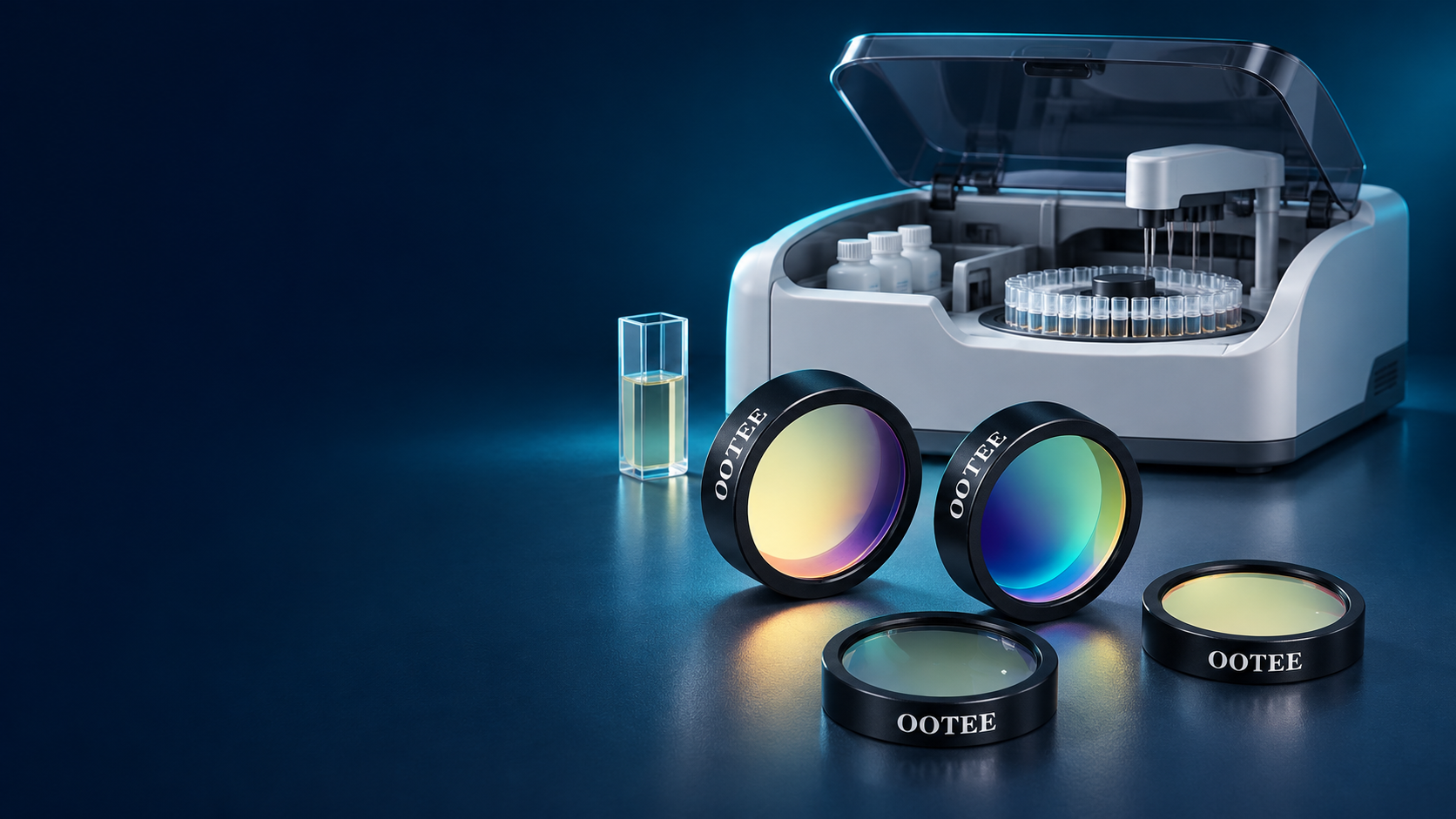
A biochemistry analyzer measures the absorbance of the reaction mixture in a defined band, or its change over time. The filter sets which part of the spectrum actually reaches the measurement chain, so it has to be matched to the reagent method and to the optical design of the instrument.
| System concern | Filter selection focus |
|---|---|
| Wavelength matched to the reaction chemistry | Center wavelength, tolerance and passband range |
| Limited flux in the UV channel | Substrate transmission, coating design and full-chain response |
| Stray light matters more at high absorbance | Blocking range and out-of-band leakage |
| Drift during continuous readings | Spectral stability, thermal environment and mounting |
| Matching across channels and instruments | Lot control of wavelength, bandwidth and transmission |
Filters are validated inside the complete measurement system. Accuracy, linearity, repeatability and drift also depend on the source, detector, cuvette, temperature control and calibration routine.
The filter position changes with front-end, rear-end or multi-channel architectures; the diagram follows the target layout.
Absorbance is read at a defined reaction condition and time point.
The absorbance change is measured over a defined interval.
The signal is sampled continuously and the reaction rate is derived.
All three methods need appropriate spectral selection. For continuous readings, the stability of the whole chain over the measurement period matters as well.
The wavelengths below are navigation directions; the live page lists the models actually available.
UV channel for clinical chemistry — transmission, blocking and stability
Near-UV and short visible channels set by instrument and reagent method
Channel for colorimetric biochemistry methods
Specified separately according to the actual spectral need
Colorimetric detection in the green region
Selected by reaction chemistry and instrument configuration
Long visible measurement or reference channel
Extended channels assessed against architecture and method
These wavelengths are configurations different instruments may use; they are not one unified standard. Neighbouring wavelengths are not interchangeable just because the numbers are close.
Some methods based on NADH / NADPH read absorbance change around 340 nm. This channel has to be assessed across the whole chain — source output, filter, reaction vessel and detector response in the UV.
| Focus | What to check |
|---|---|
| UV transmission | Choose substrate and coating for the working band, then confirm the transmission of the finished part. |
| Full blocking range | Beyond the passband edges, check leakage across the whole region where the source emits and the detector responds — a local slice of spectrum does not describe blocking. |
| Stability in use | Verify transmission and spectral change under the actual illumination, temperature and humidity conditions. |
| Flux match in the instrument | Judge the usable signal after mounting, together with the UV transmission of the cuvette or flow cell. |
This channel is defined by source, filter, vessel and detector together. Validate it in the instrument; do not infer measurement results from single-part specifications.
From single filters to multi-wavelength sets, chosen by channel count and mechanical layout.
UV measurement channel
Colorimetric channel
Dual-wavelength measurement as the method requires
Analyzer modules running many assays
Specific filter wheels and assemblies
A reference wavelength filter is a bandpass filter assigned to that role. Dual-wavelength schemes follow the method; no fixed pair covers every assay.
Set by the absorption characteristics of the reaction product and by the method — not by the instrument channel name alone.
A wider band passes more light but also widens the spectrum taking part in the measurement; a narrower one may cost signal. Balance the two.
When the sample absorbs strongly in the target band, even a small amount of out-of-band light can shift the result. Set blocking from source, detector and measurement range.
State whether the figure is peak, average or minimum, and judge usable flux against the actual source spectrum.
Interference filter spectra shift with angle. Provide working angle, cone angle and clear aperture.
Set temperature, humidity and thermal load from where the filter is actually mounted, and define the spectral acceptance range.
These are the ranges we normally produce. Requirements beyond them can be evaluated from drawings; final values are confirmed by sample and datasheet.
| Specification | Range we can produce |
|---|---|
| Standard wavelengths | 340, 380, 405, 450, 480, 505, 546, 570, 600, 630, 700 nm |
| Bandwidth (FWHM) | 8-12 nm, narrow and high precision |
| CWL tolerance | ±1 nm for assay repeatability |
| Blocking depth | OD3-OD4 |
| Transmission | T >70% |
| Clear aperture | φ10-φ20 mm |
| Wavelength stability | Annual drift below 0.5 nm |
Supporting material includes zoomed passband and full-range blocking curves, multi-wavelength overlay plots, dimensional drawings with mounting orientation, test reports or datasheets, and lot-consistency data where it exists. Instrument absorbance accuracy is not presented as a single-filter specification.
Filter and set selection by architecture, channel count and available space.

Multi-wavelength measurement channels configured for the assay menu.

Selection around the flow cell, filter wheel and photodetector module.

Balancing size, flux, channel count and assembly constraints.

Filters configured to the specific method and optical layout.

Wavelength and path assessed against the actual measurement; scattering layouts confirmed separately.
Requirements → spectral and mechanical assessment → sample set → system validation → specification release
Collect working wavelength, bandwidth, source, detector and mounting conditions.
Define blocking range, clear aperture, substrate and assembly requirements.
Prepare the sample combination to the agreed spectral and mechanical spec.
Confirm filter spectra first, then check absorbance accuracy, linearity, repeatability, drift and kinetic behaviour per the instrument procedure.
Fix single-part acceptance, lot consistency, packaging and delivery terms.
This block uses real inspection equipment, sample reports and manufacturing capability.