
Transmission / reflection
Mark the transmitted and reflected direction of every dichroic — "long-pass" alone is not enough.
Multicolor flow · Cell sorting · Spectral flow
Matched to lasers, fluorochromes and detectors for multicolor flow detection.
Bandpass filters, long-pass / short-pass splitters and laser-rejection filters are configured around multi-channel fluorescence collection. Dye spectra, optical layout and detector response set the balance between collection efficiency, laser-leakage rejection and cross-channel response.
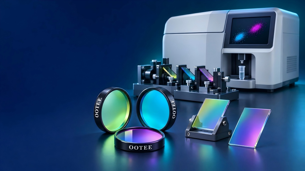
Cells or particles passing the laser intercept produce scatter and fluorescence. The optics collect these signals and route them to detectors according to the measurement. Filters and splitters work with the whole path to define what each channel actually responds to.
| System concern | Filter design focus |
|---|---|
| Collecting weak fluorescence | Passband position, bandwidth and transmission of the whole path |
| Scattered laser reaching fluorescence channels | Blocking near the laser line and the leakage path |
| Overlapping emission of several dyes | Passband versus the response of neighbouring channels |
| Cumulative loss across splitting stages | Transmission and reflection of each dichroic |
| Matching across instruments and lots | Consistency of edges, transmission and mounting |
Sensitivity and population resolution also depend on the lasers, collection optics, fluidics, detectors, reagents and data processing — confirm them by system-level validation.
Fluorescence and scatter channels are configured to different goals: the former rejects scattered laser light, the latter measures it.
Mark the transmitted and reflected direction of every dichroic — "long-pass" alone is not enough.
Mark the passband of each channel and its overlap with neighbours.
Draw multi-laser systems at their actual excitation points and collection geometry.
Fitted only where the source and system actually need them.
Fluorescence channels usually have to reject scattered laser light; scatter channels have to measure signal near the laser wavelength. Configure the two to different targets.
The table below shows selection directions; real channels are confirmed against dye and instrument layout.
UV excitation conditions and separation of several emission channels
Short-wavelength collection and violet rejection
Green collection and blue leakage control
Channels from yellow-orange to far red
Red rejection and far-red collection
These are selection directions, not the only excitation option nor a complete compatibility list. Confirm against the specific dye, laser line, reagent panel and instrument layout.
Grouped by function in the path; dichroics and final bandpass filters are selected together.
Defines what each detector collects
Routes bands to the intended path
Keeps a laser line out of fluorescence channels
Selects the scatter detection band
Adjusts intensity in scatter and similar channels
Matches a complete splitting chain
Dichroics and final bandpass filters are selected together. The nominal passband of the last filter is not the effective passband of the whole path — earlier splitters change the final response.
Choose the collection window from the full emission spectrum, not from the emission peak alone.
A wider band collects more target signal but can also admit other dyes. Assess it against the actual multicolor panel.
Set blocking for the laser wavelengths that can reach that channel, and check performance after the angle changes.
Work out the effective transmission after each reflection or transmission, and watch the loss near splitting edges.
Dichroics work at a specified angle. State the actual angle, cone angle and polarization — do not substitute a normal-incidence curve.
Control spectral edges, transmission and mounting variation, and verify in the module. Changing a filter can change channel response and compensation.
These are the ranges we normally produce. Requirements beyond them can be evaluated from drawings; final values are confirmed by sample and datasheet.
| Specification | Range we can produce |
|---|---|
| Standard lasers | 405, 488, 561, 638, 780 nm |
| Fluorescence channels | FITC, PE, PerCP, APC, Pacific Blue and further multicolour combinations |
| Dichroic mirrors | Longpass / shortpass dichroic at 45° incidence |
| Emission filters | Narrow bandpass matched to each fluorescence emission peak |
| Blocking depth | OD5-OD6 for high channel isolation |
| Channel cross-response | Defined and verified per dye, concentration, laser and detection condition; not quoted as a blanket value |
| Clear size | 25×36 mm standard, or customised to the flow cell |
Show channel transmission curves, dichroic transmission and reflection curves, blocking near the laser line, dye emission overlaid with channel response, plus dimensional drawings and mounting orientation. Keep schematic and measured curves clearly separated.
Spectral flow records the spectral signature of fluorescence across many channels and then unmixes it against reference signals. Filter and splitter design has to consider how the bands cover each other and how consistent the overall response is.
| Focus | What it involves |
|---|---|
| Bands and overlap | Set detection bands and the overlap between channels to the architecture. |
| Cumulative transfer and response spread | Assess cumulative transmission and response differences across channels. |
| Band edges and lot variation | Control band edges and variation between lots. |
| Unmixing workflow validation | Validate with the detector array, calibration and unmixing procedure. |
The "one dye, one bandpass filter" logic does not carry over to spectral flow.
Filters and splitters configured to lasers, dyes and splitting architecture.
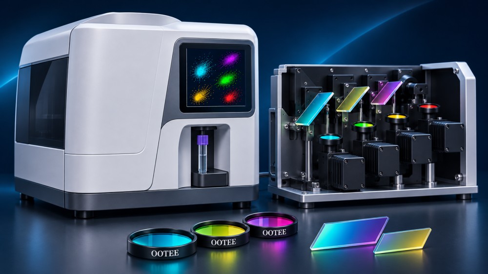
Fluorescence channels configured to the laser and dye panel.
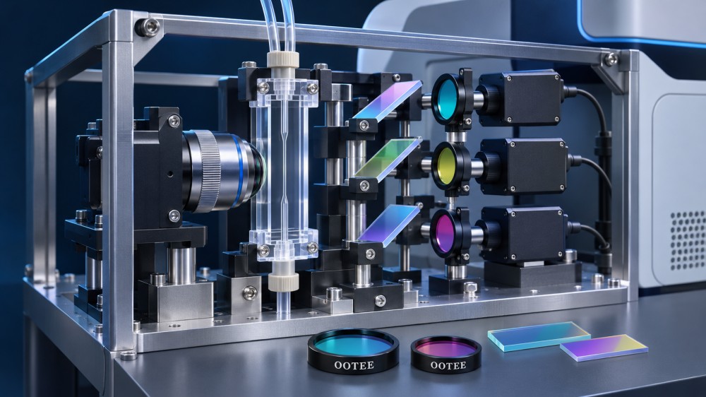
Filters and splitters arranged around signal collection before sorting.
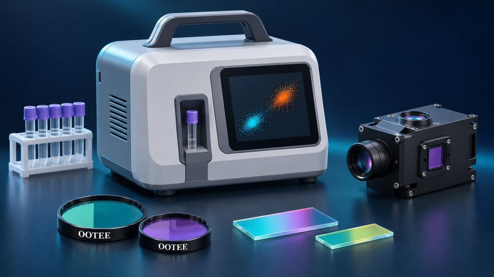
Balancing size, channel count and usable flux.
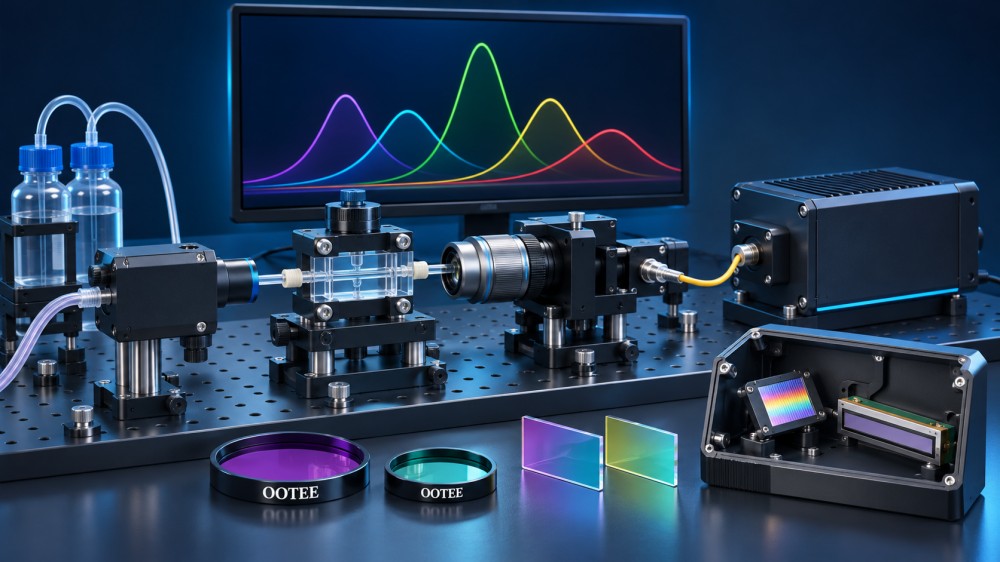
Assessing the full optical response for multi-band architectures.
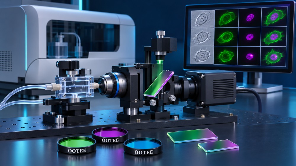
Selected separately for imaging channel, field and wavefront requirements.
Requirements → spectral and path assessment → sample set → module validation → specification release
Collect laser configuration, dye list, detector response, existing channel table and mechanical constraints.
Evaluate dichroics and bandpass filters together: blocking regions, passbands and the order of splitting.
Assemble the channel combination to the agreed assessment.
Using suitable blank, single-stain and control material per the system procedure, check background, laser leakage, channel response and repeatability; multicolor or spectral systems additionally verify compensation or unmixing.
Fix spectral acceptance, mounting orientation, lot consistency and post-replacement verification.
This block uses real equipment photos, sample reports and delivery documentation.