
01
340 nm
UV detection — substrate, source and detector compatibility conditions
- CWL
- Per model
- FWHM
- Per assay
- Size
- Per mount
ELISA · Colorimetric assays · Enzyme kinetics
Measurement wavelength selection and matched filter sets for microplate absorbance detection.
For ELISA, colorimetric analysis and enzyme kinetic assays, we configure measurement- and reference-wavelength filters against the assay method, source spectrum and detector response. Sensible bandwidth and out-of-band blocking design provides a stable spectral selection basis for the reader optical module.
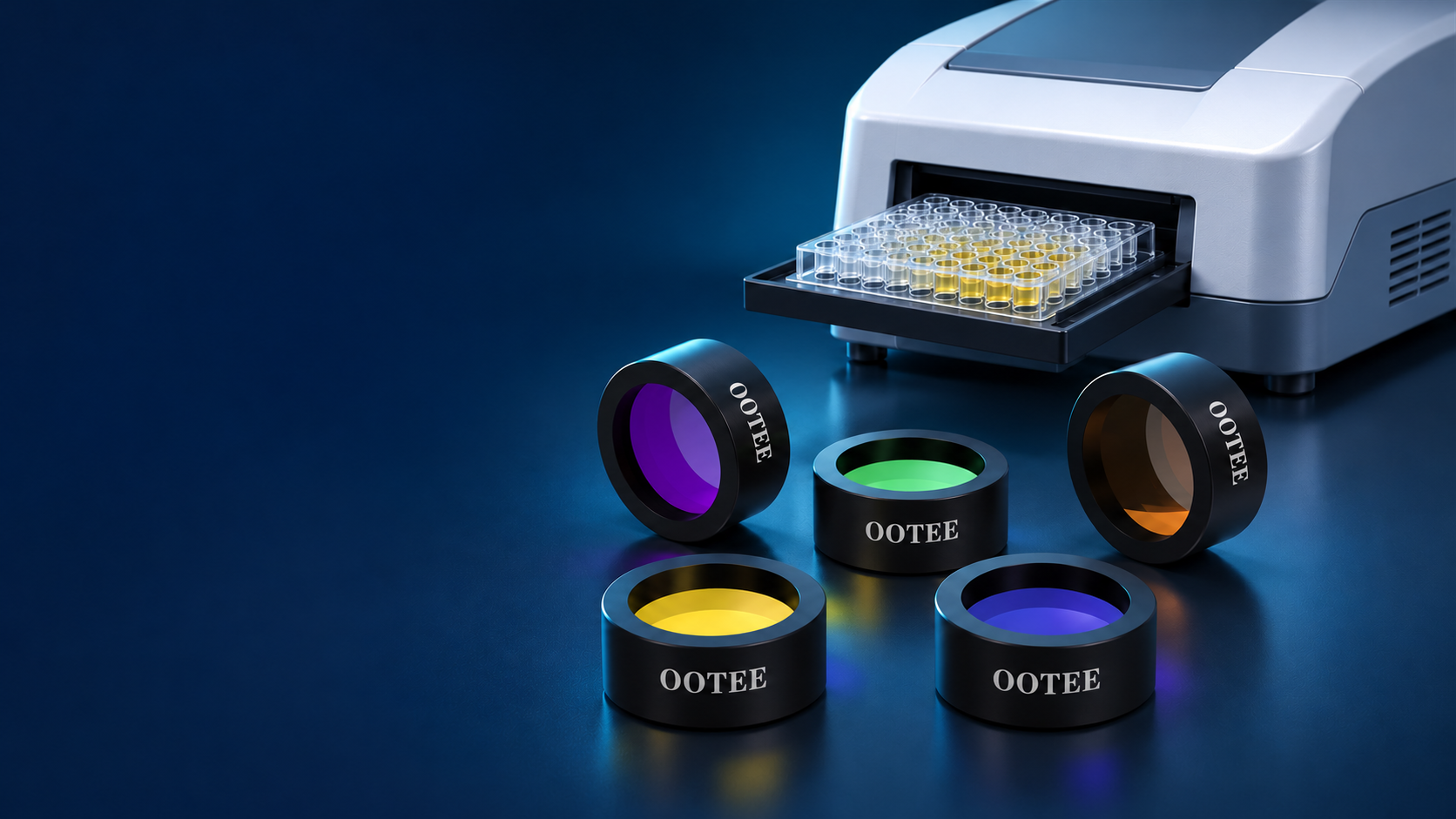
An absorbance microplate reader analyses how much light the sample absorbs in a given band. Filter centre wavelength, bandwidth and out-of-band leakage all affect the spectrum that actually reaches the measurement, so they have to be matched to the assay method and the instrument light path together.
| System concern | Filter design focus |
|---|---|
| Measurement wavelength matching the assay | Centre wavelength, wavelength tolerance and usable passband |
| Unwanted light affecting the reading | Out-of-band blocking across the source and detector range |
| Insufficient flux or unstable readings | Balancing passband transmission against bandwidth |
| Well-to-well or channel differences | Working angle, clear aperture and spectral uniformity |
| Consistency across instruments and batches | Acceptance criteria for wavelength, bandwidth and transmission |
Absorbance accuracy, linearity and repeatability are properties of the complete instrument and must be verified together with the source, detector, stray light, sample and calibration procedure.
The groups below are navigation directions; the range actually shown follows the models available.
UV detection — substrate, source and detector compatibility conditions
Narrowband specifications for the corresponding assay method
Common ELISA measurement wavelength
Colorimetric measurement wavelength
Visible detection configured per assay method
Filter set for the corresponding colorimetric method
Measurement or reference wavelength depending on the method
The same wavelength can serve different assay methods, and a reference wavelength is not a fixed universal configuration. Always follow the reagent instructions and instrument requirements.
A typical path is shown above; the actual element order follows the instrument architecture.
Matched to the detection requirement of the target chromogenic product.
Selected per assay method for the specified background correction.
Handles reagent, microplate and other background according to the method.
Reference-wavelength correction and blank correction do different things — one cannot replace the other.
From single filters to complete filter-wheel sets, chosen by channel count and mounting structure.
Selects the measurement band
Selects the reference band specified by the method
Provides several detection channels
Fits a specific mounting envelope
Supports module assembly
A reference-wavelength filter is a bandpass filter specified by its use. Multi-wavelength sets require the spectral and mechanical specification of every channel to be confirmed separately. Framing and filter-wheel assembly services are shown only where the delivery capability actually exists.
Set the target wavelength from the assay method and assess the allowed deviation against the shape of the absorption spectrum.
A narrower passband defines the measured spectrum better but passes less energy; a wider one may average the spectrum more. Choose against sample absorption and the instrument signal budget.
Blocking must cover the region where the source emits and the detector responds. Quoting OD at a single wavelength does not describe stray-light control completely.
State whether peak, average or minimum is meant, and judge the usable flux against the actual source output.
Interference filter spectra shift with angle of incidence. Provide mounting angle, beam cone angle and clear aperture to assess the response across the beam.
Confirm substrate and coating requirements against real temperature, humidity, source thermal load and assembly conditions, and set batch acceptance criteria for wavelength, bandwidth and transmission.
These are the ranges we normally produce. Requirements beyond them can be evaluated from drawings; final values are confirmed by sample and datasheet.
| Specification | Range we can produce |
|---|---|
| Detection modes | Absorbance (colorimetric), fluorescence (excitation + emission), chemiluminescence |
| Common wavelengths | 340, 405, 450, 490, 520, 560, 620, 650 nm |
| Bandwidth (FWHM) | Absorbance 10 nm; fluorescence excitation 10-20 nm; emission 20-30 nm |
| Blocking depth | OD3-OD5 |
| CWL tolerance | ±2 nm |
| Clear size | 25×25 mm standard, or customised to the filter wheel |
| Aperture uniformity | Transmission variation across the aperture within ±2% |
Every chart states the test angle, test range and data nature — typical, guaranteed or measured.
Typical adaptation directions; model compatibility requires supporting evidence.

Select measurement and reference wavelengths from the chromogenic system and stop conditions.

Configure detection channels from the assay method and the absorption spectrum of the target product.

Assess flux and stability around the specified measurement wavelength and continuous reading requirements.

Matched selection considering mounting space, filter-wheel structure and multi-channel needs.
Microplate readers with fluorescence capability need excitation and emission bands configured per dye; coaxial paths can add a dichroic mirror as designed.
| Element | Function |
|---|---|
| Excitation filter | Selects the excitation band of the target dye |
| Emission filter | Collects target fluorescence and suppresses excitation leakage |
| Dichroic mirror | Combines or splits excitation and emission as the path requires |
This module is presented separately from the absorbance products, with its own specification table and enquiry entry.
Requirement → spectral and mechanical assessment → sample set → instrument verification → specification release
Detection mode, assay method, measurement and reference wavelengths, source and mounting structure.
Confirm wavelength, bandwidth, blocking range, working angle and dimensions.
Supply the filter samples or matched set to be verified.
Measure the filter spectra first, then assess absorbance accuracy, linearity, repeatability and well-to-well consistency through the instrument verification procedure.
Set acceptance criteria, assembly requirements and batch delivery conditions from the test results.
Images for this module preferably show real spectral test equipment, inspection reports and assembled samples.