
Around 840 nm OCT
Bandwidth transmission and auxiliary-channel separation for the corresponding near-infrared source.
- Inputs needed
- Measured source spectrum, usable bandwidth, detector response
Ophthalmic OCT · Low-coherence interferometry
Working-bandwidth transmission, multi-band beam splitting and stray-light control — matched to the optical path of ophthalmic OCT systems.
For ophthalmic optical coherence tomography systems, we configure near-infrared filters and dichroic components against the real source bandwidth, angle of incidence and imaging architecture. Selection weighs spectral transmission, wavefront quality and dispersion, and supports integration of OCT with auxiliary imaging channels.
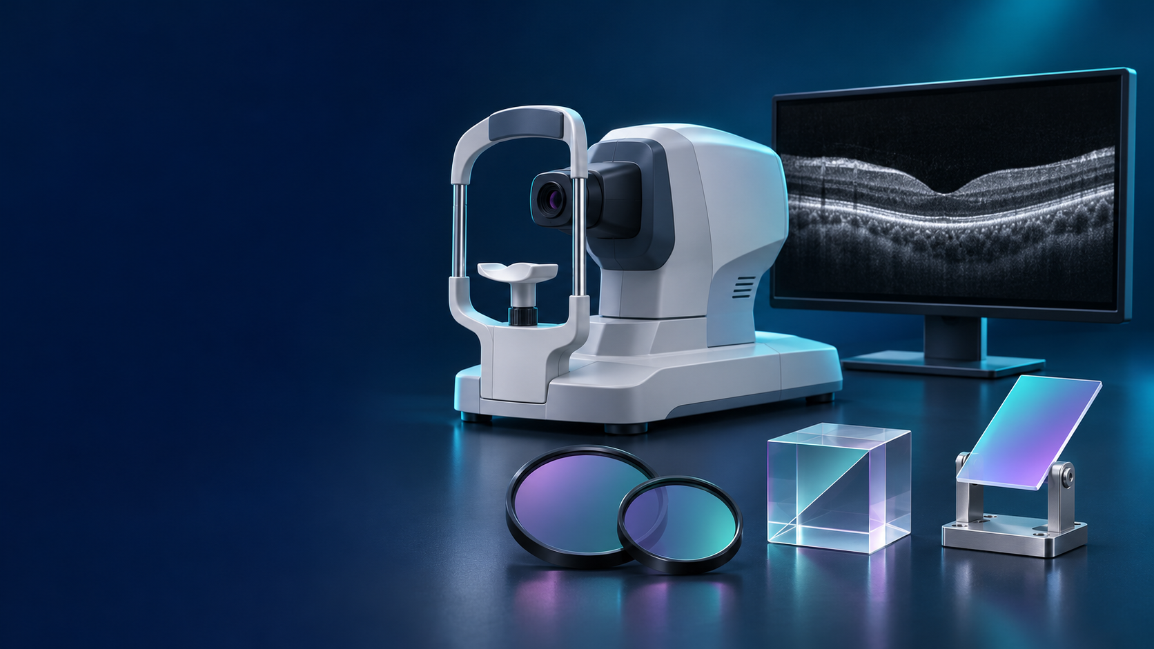
OCT derives depth information from interference between sample and reference light. Filtering and beam-splitting components must follow the system spectrum and interferometer layout, so that useful bandwidth is not truncated by accident and added reflection or dispersion does not degrade the signal.
| System requirement | Component focus |
|---|---|
| Transmit the complete working spectrum | Passband coverage, edge position and transmission ripple |
| Separate OCT from auxiliary imaging channels | Dichroic transmission / reflection bands, transition zone and working angle |
| Suppress out-of-band background | Identify the stray-light source and the corresponding blocking range |
| Control parasitic reflection and ghost images | Surface reflection, coating, substrate and mounting method |
| Preserve interference signal quality | Dispersion matching between sample and reference arms, and wavefront effects |
The value of a filter depends on where and how it is mounted — confirm the configuration against the real optical path.
Typical entry points; exact wavelengths follow the actual project.
Bandwidth transmission and auxiliary-channel separation for the corresponding near-infrared source.
Transmission across the full sweep range of the corresponding swept source.
Assessed independently for the source used in the project.
Combining and separating OCT from fundus viewing, alignment and fixation channels.
Centre wavelength only serves as a first sorting key and cannot replace a full passband specification. For swept-source systems, the actual sweep range must be covered.
Source → coupling / splitting unit → sample arm and reference arm → recombination of returned light → detection unit
Sample arm: OCT path → dichroic combining element → scanning and ocular imaging optics
Component position and function differ between OCT architectures. SD-OCT and SS-OCT detect the signal differently, so their transmission / reflection requirements and mounting positions should be checked separately rather than covered by a single detector-end diagram.
Schematic only; component count, position and splitting direction follow the system architecture.
Filtering, splitting and ancillary parts each have a role; the combination follows the system architecture.
Transmits the target working band and rejects out-of-band light.
Isolates selected bands as required.
Combines or splits the OCT and auxiliary channels.
Adjusts optical power as required.
Structural isolation or protection.
Attenuation used for power adjustment must be folded into system-level power control and verification. Fibre couplers or interferometric splitters should be described separately from dichroic mirrors used for band separation.
Define the passband from the effective spectrum of the source and detection chain. For swept sources, check the entire sweep range rather than transmission at the centre wavelength alone.
Filtering changes the spectral weighting of the system. Look for bandwidth truncation, local dips or pronounced ripple, and evaluate them against the system axial point spread function.
Substrate material, thickness and coating can introduce dispersion. For components inside the interferometer, assess against their position and the difference between the two arms; agree group delay or group delay dispersion where it matters.
Surface reflections can produce unwanted signal. Evaluate rear-side AR coating, wedge and tilted mounting according to position, and verify the effect on beam deviation and coupling.
Interference filter spectra shift with angle, and at oblique incidence the two polarisation states differ. Confirm performance under the actual working conditions.
Assess imaging and coupling impact together with beam diameter, clear aperture, flatness, thickness and fixing method.
These are the ranges we normally produce. Requirements beyond them can be evaluated from drawings; final values are confirmed by sample and datasheet.
| Specification | Range we can produce |
|---|---|
| Center wavelength | 840 nm and 1060 nm standard, customised to the light source |
| Usable bandwidth | Covers the effective source spectrum or the actual sweep range |
| Blocking depth | OD4-OD5, suppressing out-of-band stray light |
| Passband transmission | T >85% |
| Flatness | λ/4 to preserve imaging performance |
| Substrate | Fused silica (low thermal expansion) |
| Clear aperture | φ25-φ50 mm |
| Operating temperature | Wavelength drift below ±2 nm over 10-50 °C |
Every document states the model and test conditions and separates typical from guaranteed values; angle-sensitive models are supplied with curves at several angles.
Typical adaptation directions; model compatibility needs a verification basis.
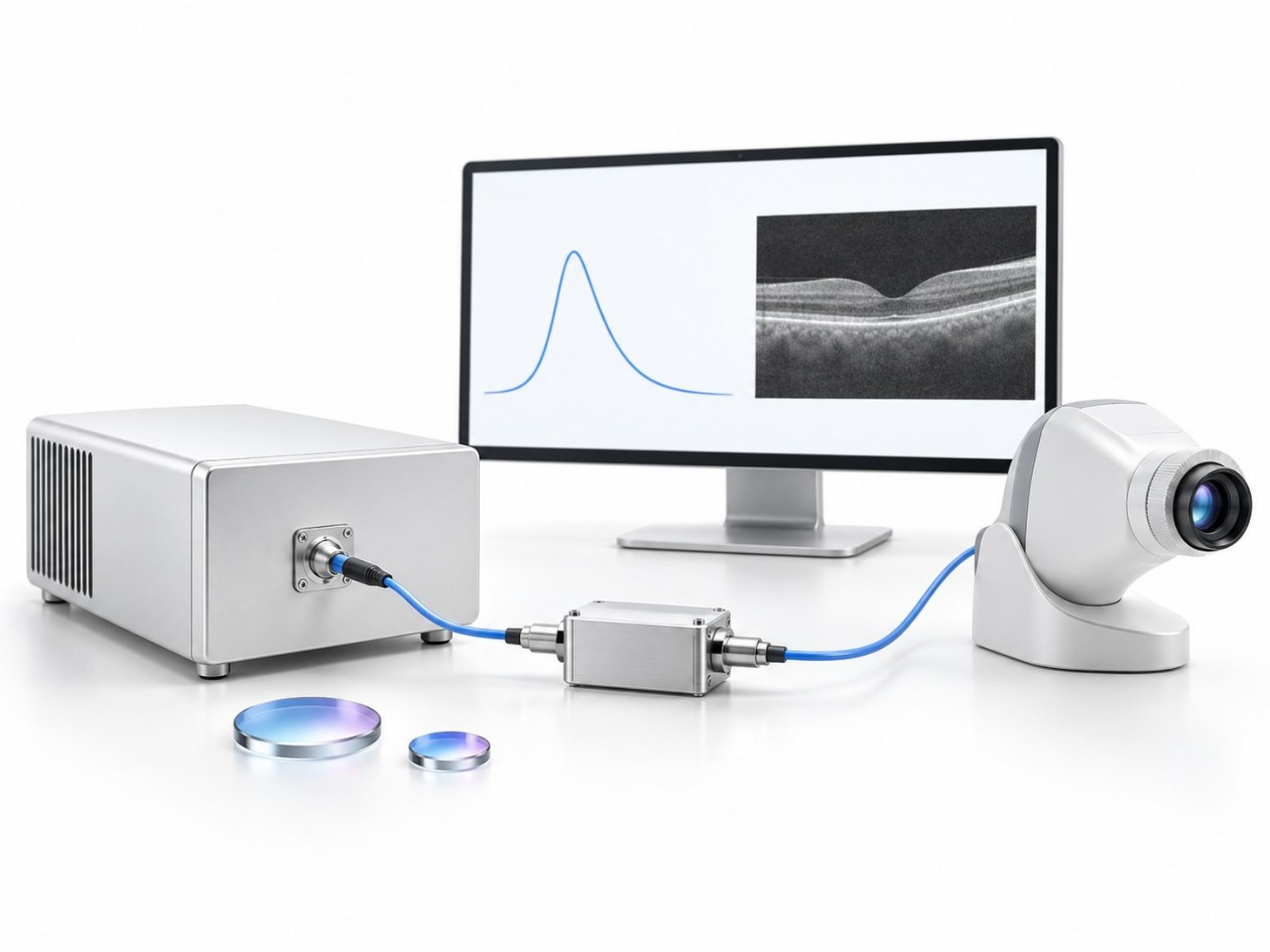
Selected around working-spectrum transmission, fundus auxiliary channel separation and mechanical integration.
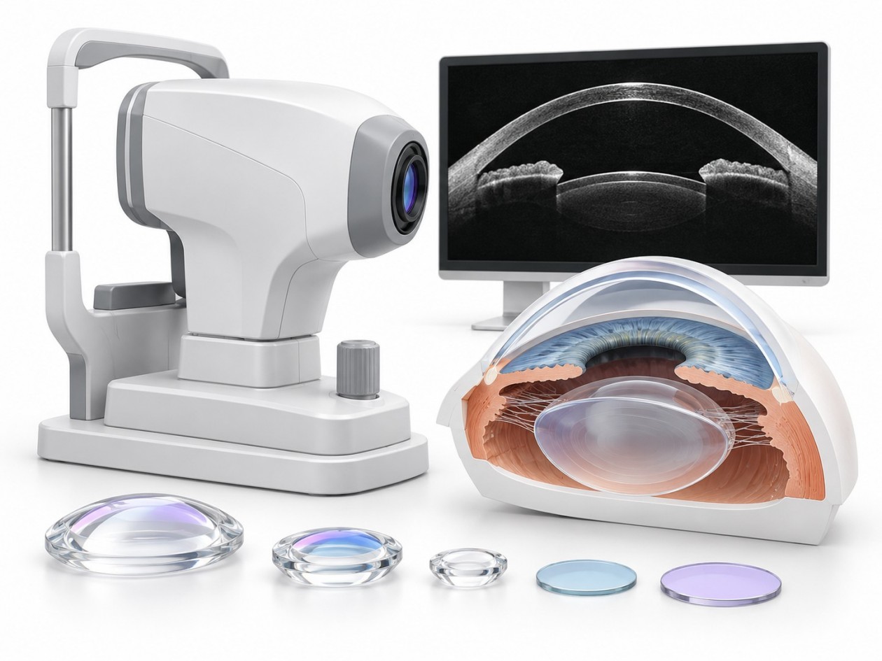
Focus on transmission and reflection across the full sweep range, plus dispersion and parasitic reflection in the path.
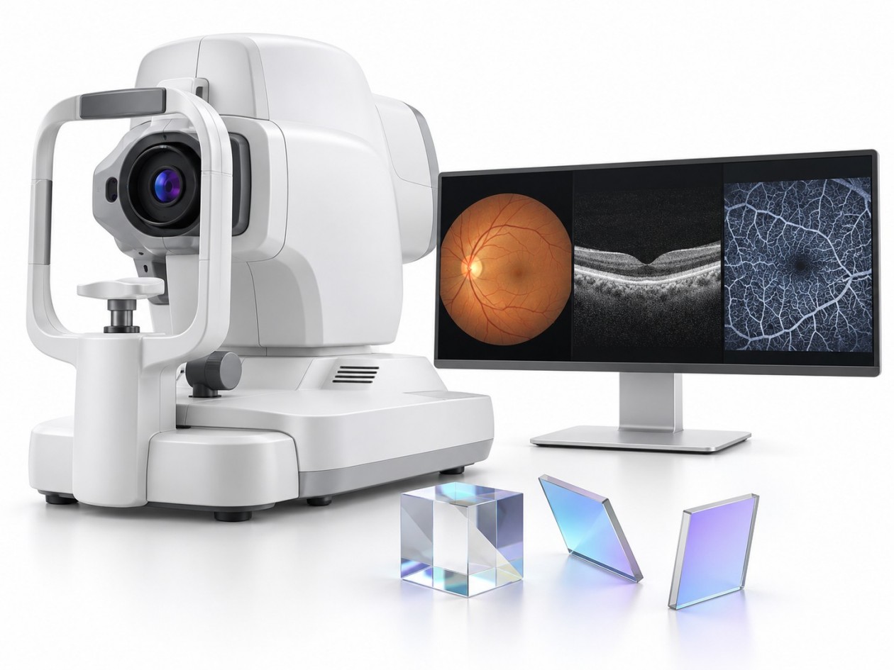
Configured against the project band, scan structure and available mounting space.
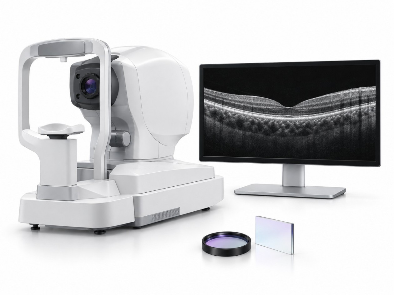
Combining and splitting designed around the relationship between OCT, viewing, alignment and other imaging channels.
Requirement → spectral and mechanical assessment → sample build → system verification → specification release
OCT type, source working range, component position, auxiliary channels and mounting conditions
Transmission / reflection bands, angle, polarisation, substrate and any dispersion requirement
Samples made to agreed parameters with measured curves
Check power throughput, axial point spread function, sensitivity, parasitic signal and channel crosstalk in the real system
Fix acceptance conditions and batch consistency requirements from the sample results
Providing the source working range, component position, auxiliary channels and mounting conditions helps identify the right filtering and splitting approach. Machining, coating, inspection and delivery capability is documented with the actual facility data.