
Excitation filter
Selects the excitation band suited to the dye and suppresses unwanted source output in the detection band.
Real-time quantitative PCR · Multichannel fluorescence detection
Excitation, emission and beam-splitting solutions matched to fluorescent dyes and the detection optical path.
Around common fluorescence channels such as FAM, HEX, VIC, ROX and Cy5, we configure excitation filters, emission filters and dichroic mirrors against the source spectrum, dye characteristics and detector response. Sensible passband and blocking design balances fluorescence collection efficiency, background suppression and the need to separate multiple channels.
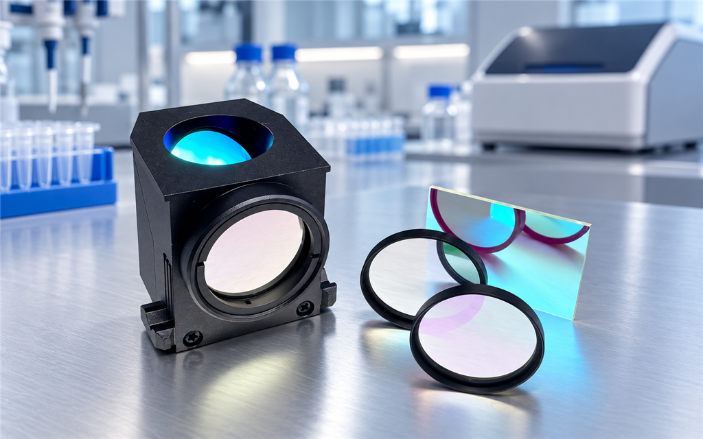
Real-time PCR analyses the fluorescence change during the reaction. Filters have to pass the target signal while suppressing excitation leakage and unwanted signal from other channels, and must match the instrument optical design and calibration approach.
| System concern | Filter selection focus |
|---|---|
| Collecting a weak fluorescence signal | Passband position, usable bandwidth and passband transmission |
| Background from excitation leakage | Blocking regions of the excitation and emission filters and their combined behaviour |
| Spectral overlap between dyes | Per-channel passband, transition width and cross-response |
| Well-to-well reading differences | Working angle, beam distribution and effective clear aperture |
| Consistency across instruments | Spectral edges, transmission and batch-to-batch consistency |
Detection sensitivity, repeatability and quantitative performance also depend on reagents, thermal control, the detector and the algorithms, and should be verified at system level.
Common channel directions; the final passband follows the dye, reagent system and detection architecture.
| Channel direction | Typical dyes | Selection focus |
|---|---|---|
| 01 Green fluorescence | FAM, SYBR Green I | Target emission collection, excitation rejection and background control |
| 02 Yellow-green fluorescence | HEX, VIC, JOE | Spectral separation from the green and neighbouring channels |
| 03 Orange fluorescence | NED, TAMRA, Cy3 | Collection range set from the specific dye and reagent use |
| 04 Red fluorescence | ROX, Texas Red | Confirm reporter or passive reference use |
| 05 Far-red fluorescence | Cy5 | Source matching, detector response and adjacent-channel crosstalk |
| 06 Extended far-red channels | Cy5.5 and others | Confirm instrument coverage and calibration conditions |
These groups support first-pass selection only. Dyes within a group do not share identical spectra, so the grouping alone does not make a filter interchangeable. The final passband is set from the specific dye, reagent system and detection architecture.
First locate the components in the optical path, then see how the three spectra work together. Non-coaxial architectures are drawn as actually designed; a three-part set is not mandatory.
A coaxial excitation and collection architecture can add a dichroic mirror to separate excitation light from fluorescence.
Selects the excitation band suited to the dye and suppresses unwanted source output in the detection band.
Selects the target fluorescence band and reduces scattered or reflected excitation light reaching the detector.
Reflects or transmits selected bands to combine or split the excitation and collection paths.
Single-channel and multichannel selection follow different logic; the combination follows the detection architecture.
Single-channel excitation band selection
Single-channel fluorescence collection
Separation of excitation and emission bands
Excitation + emission filter, dichroic added as required
Several channels configured for the target dye combination
Designed to the actual size, shape and mounting requirement
A multichannel solution should be assessed on the response of the whole set, not by comparing peak transmission of individual filters. Where multiband pass or multiband dichroic designs are used, channel switching and signal separation have to be matched as well.
Set the excitation passband from the dye excitation spectrum and the real source output — not from the dye peak wavelength alone.
A wider passband collects more target fluorescence but can also admit more background or neighbouring dye signal. Weigh it against channel count and signal budget.
The emission filter needs sufficient rejection across the actual excitation range, and the excitation filter should limit source leakage into the fluorescence detection region. OD values must be stated together with the wavelength range.
Watch for signal from other dyes being excited and entering the current detection channel. Filter selection should go together with single-dye testing, system calibration and any required spectral compensation.
Interference filter spectra shift with angle, so evaluate at the real mounting angle and beam cone. For wide fields or multi-well collection, check the incidence conditions at each position.
State the temperature, humidity and mounting conditions at the filter position. The temperature of the thermal cycler block is not the temperature the filter sees — agree requirements against the real environment.
These are the ranges we normally produce. Requirements beyond them can be evaluated from drawings; final values are confirmed by sample and datasheet.
| Specification | Range we can produce |
|---|---|
| Standard channels | FAM 470/520 nm, HEX 530/560 nm, ROX 580/610 nm, Cy5 630/680 nm |
| CWL tolerance | ±1 nm, excitation and emission controlled separately |
| Bandwidth (FWHM) | Excitation 10-20 nm; emission 20-30 nm |
| Excitation blocking | OD4-OD6 candidate for the specified stopband, not a channel crosstalk figure |
| Peak transmission | Excitation >60%; emission >70% |
| Dichroic edge steepness | Cut-off edge within 5% of the wavelength |
| Clear size | 25×36 mm standard, or customised to the instrument |
| Thermal drift | ≤0.01 nm/°C over 15-40 °C |
Every curve states the model and test conditions and whether the data is typical, guaranteed or measured.
Typical adaptation directions; model compatibility needs a verification basis.

Channels configured around the target dyes, sample format and detection method.

Cross-response between channels and dynamic range assessed for the dye combination.

A compact optical path configured against source, detector, space and power budget.

Focus on chip material background, collection area and the optical interface.

Assessed separately for the droplet or chip readout architecture. Digital PCR readout differs from real-time qPCR and is documented as a separate application.
Requirement → spectral scheme → sample set → module verification → specification release
Fix the dye combination, channel count, source, detector and mounting method
Assess passbands, blocking regions, dichroic edges and angular conditions
Supply the filter combination to be verified for the real optical path
Check background, cross-response, signal strength and repeatability with blank, single-dye and mixed samples; multi-well systems also check positional consistency
Fix acceptance criteria, mounting requirements and batch consistency standards from the system-level tests
This section is illustrated with the actual inspection equipment, spectral reports or sample photographs; machining, coating, inspection and delivery capability is documented with the real facility data.