
≥90% high transmission
In-band transmission of ≥90% delivers a stronger signal at the same exposure and cuts the required illumination power.
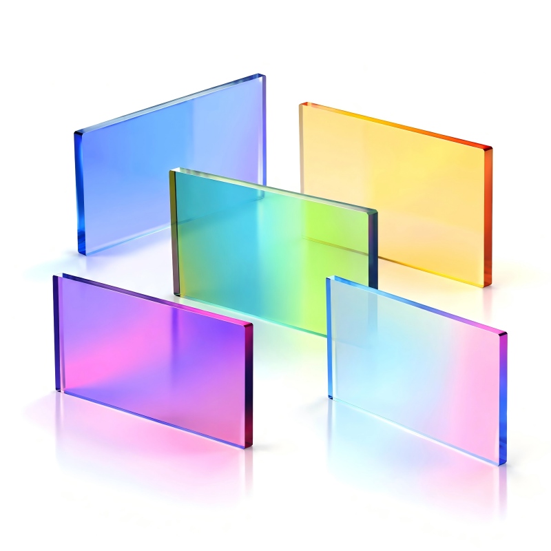
505nm Shortpass Dichroic Mirror; passband 350-495nm; transmission >90%; reflectivity >95%; size 25.4×35.6×1.1mm; AOI 45°.
505nm Shortpass Dichroic Mirror is a Dichroic Mirror engineered for beam splitting at 45° incidence, passband 350-495nm, ≥90% peak transmission, AOI 45°.
In-band transmission of ≥90% delivers a stronger signal at the same exposure and cuts the required illumination power.
Deposited by ion-assisted deposition (IAD) for a dense hard coating with low moisture uptake, minimal wavelength drift and good batch-to-batch repeatability.
| Passband | 350–495nmCustom |
|---|---|
| Cut-off Band | 515–900nmCustom |
| Transmission | >90% |
| Reflectivity | >95% |
| Dimensions | 25.4×35.6×1.1mmCustom |
|---|---|
| Dimension Tol. | +0.0/-0.1mmCustom |
| Substrate Thickness | 1.1mmCustom |
|---|---|
| Surface Quality | 60/40 |
| Coating Process | Ion-assisted deposition (IAD)Custom |
| AOI | 45°Custom |
|---|
Note: standard-part measured values. Centre wavelength, outline dimensions and blocking depth can all be made to your drawing.
No online curve data for this model yet — we are uploading it. The interactive chart appears automatically once the data is in.
Request the spectrum dataEvery parameter can be customised; samples in 2-4 weeks with tiered production pricing.
Got a drawing and a spec sheet? Send them over — our engineering team will return a feasibility assessment and a quote.
excitation/emission separation in fluorescence microscopes, flow cytometry, coaxial illumination
covering 350-495nm; A dichroic edge moves with angle of incidence: roughly a few nm per degree, so it must be specified at the real AOI, and for polarised light the S and P transition bands differ.
505nm Shortpass Dichroic Mirror splits light by wavelength at 45° — directing excitation light to the sample while returning emitted fluorescence to the detector. It is widely used in the excitation/emission paths of fluorescence microscopes, in-vivo imaging, flow cytometers and confocal systems.
Documents are being added continuously; contact us if you need one right away.
Mainly excitation/emission separation in fluorescence microscopes, flow cytometry, coaxial illumination. Final suitability depends on your actual wavelength, bandwidth and blocking requirements — send us the instrument model or channel specs and we will confirm.
Yes. Centre wavelength, bandwidth, blocking depth, substrate material, outline dimensions and mounting style (ring-mounted, threaded, square …) can all be made to your drawing. Samples usually take 2–4 weeks; production lead time depends on quantity.
Standard items ship from stock with an MOQ of one piece; custom parts are scheduled after drawing approval, with MOQ and tiered pricing scaling down by batch size — see the quotation for exact figures.
Check three things: whether the working band matches your detection wavelength, whether the band overlaps adjacent channels, and whether the blocking depth meets your background suppression requirement. Send us those three and we will advise directly.
Never touch the coating with bare hands. Clean with a lint-free cloth or swab slightly moistened with anhydrous ethanol, store in a dry clean place, and avoid concentrated stress on the coated surface during mounting.