Original content by the OOTEE Optics editorial team, drawn from first-hand production line and inspection data. Please credit the source when republishing.
Given limits in expertise and test conditions, the theories, parameters and conclusions here carry no guarantee of absolute accuracy. For technical learning and exchange only - never the sole basis for design, acceptance or selection. Corrections welcome.
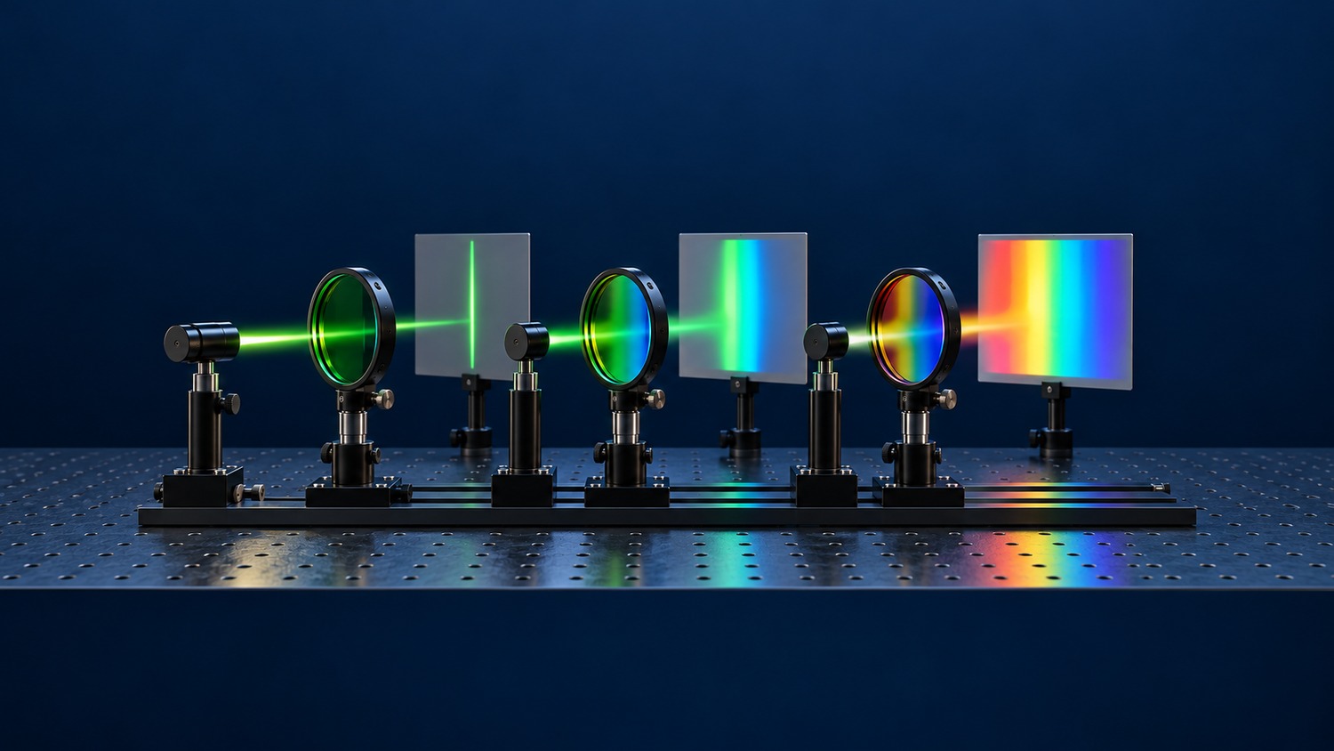
A bandpass filter transmits a bounded wavelength interval and attenuates wavelengths on either side. Narrow, medium and broad versions serve different measurement goals. A narrow window isolates a spectral line; a broader one can preserve an emission band or collect a useful region of a continuous spectrum.
Center wavelength (CWL) locates the window. Full width at half maximum (FWHM) measures its width at half the peak transmission. Here, 10 nm, 40 nm and 120 nm windows centered at 780 nm illustrate a continuum of choices, rather than universal category boundaries. Relative bandwidth matters too: 20 nm represents a different fraction of the spectrum in visible and mid-infrared systems.
Multilayer dielectric interference produces a transmission window, with reflection and, where relevant, absorption suppressing other wavelengths. Figure 1 compares calculated windows with identical centers and peak transmission. Real coatings can also show ripple, asymmetric edges and remote leakage bands.
$$T(\lambda_1)=T(\lambda_2)=\frac{T_{\mathrm{peak}}}{2},\qquad \mathrm{FWHM}=\lambda_2-\lambda_1$$
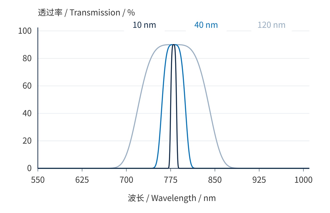
Figure 1 uses a fourth-order super-Gaussian intensity model, sampled every 0.5 nm, with 90% peak transmission and a 780 nm center at normal incidence. Only FWHM changes. These ideal comparisons are neither coating measurements nor blocking guarantees.
Optical density (OD) specifies attenuation at a wavelength. Transmission in the equation is a fraction, so OD6 means 0.0001% transmission. Always specify the wavelength interval over which blocking applies. Angle of incidence (AOI), cone angle, polarization and temperature also affect the installed spectral window.
$$\mathrm{OD}(\lambda)=-\log_{10}T(\lambda)$$
Bandwidth becomes more useful when related to detected signal. With incident signal photon spectrum $s(\lambda)$ and detector quantum efficiency $\eta(\lambda)$, the signal electron rate is:
$$N_{\mathrm{s}}=\int s(\lambda)T(\lambda)\eta(\lambda)\,\mathrm{d}\lambda$$
Background requires a separate integral using its own spectrum. Once the desired signal fits inside the window, widening may admit background without adding useful signal. Conversely, narrowing a broad emission band discards useful photons. Whether this improves precision depends on the balance of background shot noise, signal shot noise and read noise.
Figure 2 starts with the signal envelope and finishes with installed verification. Specify a guaranteed transmission interval and a minimum transmission within it. FWHM boundaries alone do not define a high-transmission plateau.
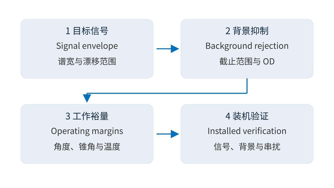
For a signal spanning 775–785 nm, CWL 780 nm and FWHM 20 nm could be a starting point. Add a minimum transmission requirement across the signal interval and margins for center tolerance and angle shift. An OD6 requirement over 400–740 nm and 820–1100 nm would still leave transition regions to define. This is an evaluation example, not a complete product specification.
| Task | Example window | Main trade-off |
|---|---|---|
| Single-line active illumination | CWL 850 nm; FWHM 10 nm | Reject ambient light while accommodating source drift |
| Fluorescence collection | CWL 530 nm; FWHM 40 nm | Collect emission without excitation leakage or adjacent-channel overlap |
| Broad-spectrum imaging or band integration | CWL 780 nm; FWHM 120 nm | Preserve throughput while controlling out-of-band response |
These values are discussion starting points. Single-line sensing emphasizes stable overlap with the source. Fluorescence channels require attention to both excitation rejection and neighboring emissions. Broad-spectrum measurements place greater weight on average transmission, ripple and detector-weighted response. A broad passband can still require deep blocking on both sides.
Evaluate source spectrum, filter transmission and detector response on the same wavelength axis, then repeat the assessment across operating angles and temperatures. The appropriate window retains the required information while keeping unwanted light under control.
 365nm Narrow Bandpass Filter | Ø50mm | T>90%
OT-HBP3659050
365nm Narrow Bandpass Filter; FWHM 10nm; transmission >90%; blocking OD5; size Ø50mm; AOI 0°.
 450nm Narrow Bandpass Filter | Ø50mm
OT-HBP4509050
450nm Narrow Bandpass Filter; FWHM 10nm; transmission >90%; blocking OD5; size Ø50mm; AOI 0°.
 525nm Narrow Bandpass Filter | Ø50mm
OT-HBP5259050
525nm Narrow Bandpass Filter; FWHM 10nm; transmission >90%; blocking OD5; size Ø50mm; AOI 0°.
Send us your drawing and spectral targets — an engineer replies with a feasibility check and quotation within one business day.