Original content by the OOTEE Optics editorial team, drawn from first-hand production line and inspection data. Please credit the source when republishing.
Given limits in expertise and test conditions, the theories, parameters and conclusions here carry no guarantee of absolute accuracy. For technical learning and exchange only - never the sole basis for design, acceptance or selection. Corrections welcome.
Fused quartz is an almost entirely amorphous form of silicon dioxide. With no grains and no grain boundaries, it transmits well over an unusually wide range, from the deep ultraviolet into the near infrared. Chinese optics suppliers usually quote three grades — JGS1, JGS2 and JGS3 — but the dividing line is not simply "purity". What actually differs is how the glass is made, and that decides two things: metallic impurity content and hydroxyl (OH) content.
JGS1 is synthetic. A silicon-bearing precursor is hydrolysed in a hydrogen-oxygen flame, deposited layer by layer and consolidated into a boule. Metallic impurities can be held very low, which pushes the short-wavelength absorption edge to roughly 185 nm. The trade-off is a hydrogen-rich melt, so the hydroxyl content runs high. JGS2 is made by melting natural rock crystal in a hydrogen-oxygen flame. The process is mature and economical, and the short-wavelength limit sits near 220 nm. JGS3 is electrically fused in vacuum or an inert atmosphere; hydroxyl is driven down, and the long-wavelength limit moves past 3 μm.
| Item | JGS1 | JGS2 | JGS3 |
|---|---|---|---|
| Common name | Deep-UV optical quartz | UV optical quartz | IR optical quartz |
| Typical process | Synthetic fused | Flame fused | Electrically fused |
| Reference transmission range | 185–2500 nm | 220–2500 nm | 260–3500 nm |
| Hydroxyl content | Relatively high | Process and batch dependent | Usually low |
| Strongest band | Deep UV | UV and visible | NIR and SWIR |
| Typical use | DUV windows, precision optics | UV inspection, windows | IR windows, inspection systems |
Treat the ranges as reference classification, not as a promise. Suppliers define the grades slightly differently, measured data varies by batch, and the endpoints of a quoted range are nowhere near high transmission. Always work from the spectral test report issued for the specific batch.
A transmission curve is pinned at both ends. On the short side sits the electronic absorption edge; on the long side sit multiphonon absorption and the hydroxyl bands. Metallic impurities and oxygen-vacancy defects push the short-wavelength edge toward longer wavelengths, which is exactly why synthetic quartz reaches the deep UV. Hydroxyl, by contrast, has fixed absorption bands in the near infrared, and that is where a low-OH material earns its place.
Internal transmittance depends on the absorption coefficient and on thickness, and excludes surface reflection.
$$T_{\mathrm{int}}(\lambda)=\exp\left[-\alpha(\lambda)\,d\right]$$
Here $\alpha$ is in $\mathrm{cm^{-1}}$ and $d$ in $\mathrm{cm}$. Thickness therefore belongs in the loss budget: the same grade at 1 mm and at 10 mm does not deliver the same internal transmittance.
Reflection is the other loss channel. At a refractive index near 1.458, each interface reflects about 3.5 percent, so two surfaces cost close to 7 percent. Including reflection, the total transmittance takes the multiple-beam form:
$$T_{\mathrm{total}}=\frac{(1-R)^{2}\exp(-\alpha d)}{1-R^{2}\exp(-2\alpha d)}$$
where $R$ is the single-surface reflectance. When bulk absorption is small the expression approaches the simple two-surface relation; in a strongly absorbing band the exponential term dominates.
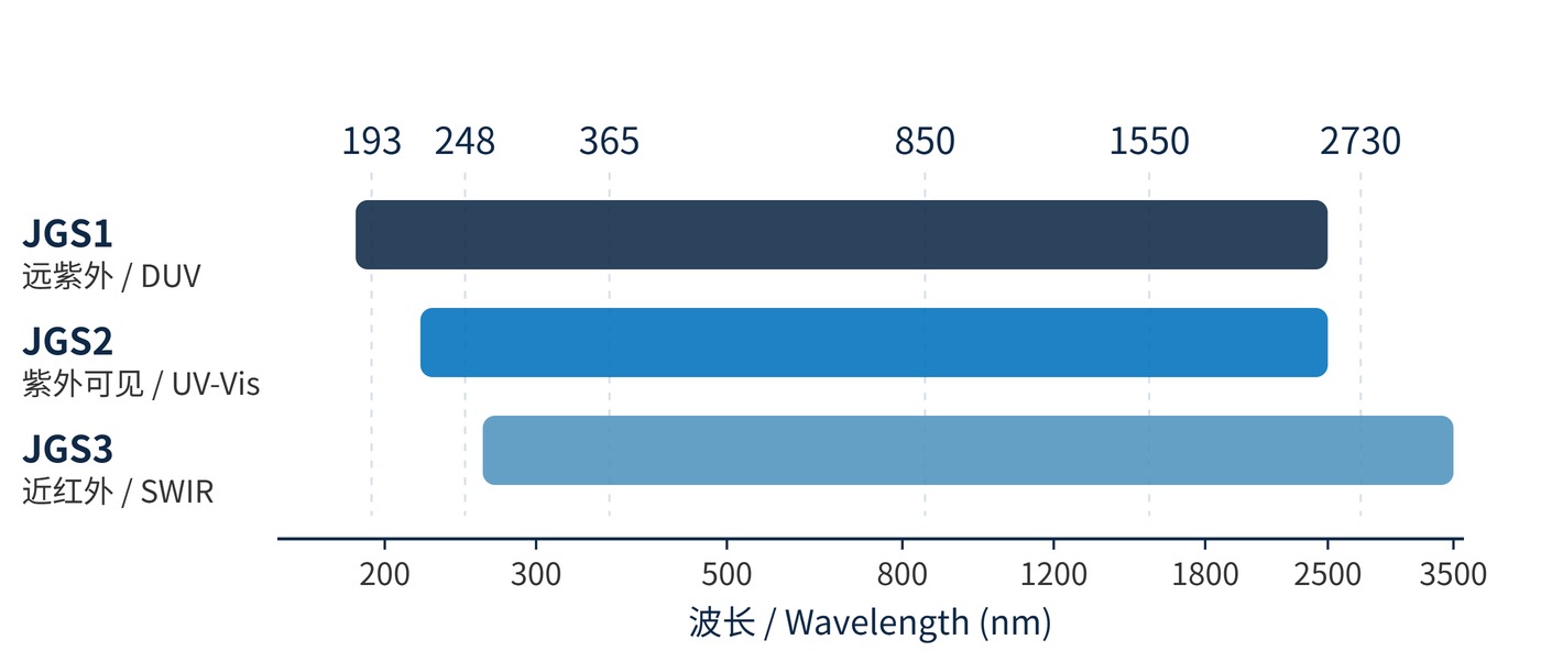
The hydroxyl bands sit in the near infrared: the fundamental near 2.73 μm, with overtones and combination bands at 1.38 μm and 2.22 μm. A low-OH grade therefore helps above roughly 1 μm, not across the whole spectrum. As Fig. 1 shows, the three bands differ mainly at the long-wavelength end and at the short-wavelength end, while overlapping heavily in the visible.
In practice, start from the wavelength and let it select the grade, then check whether the substrate parameters meet the system tolerances.
| Requirement | First choice | Also confirm |
|---|---|---|
| 193 nm deep-UV optics | JGS1 | Measured DUV transmission, ageing under exposure |
| 248 nm excimer laser window | JGS1 | Thermal lensing from absorption, surface quality |
| 365 nm filter substrate | JGS1 or JGS2 | Transmission at that wavelength, bubble and striae grade |
| 405 nm and visible windows | JGS1 or JGS2 | Dispersion data, homogeneity |
| 850 nm NIR window | Evaluate all three | Combined effect of thickness and OH absorption |
| 1550 nm laser optics | Favour low-OH material | OH absorption, bulk loss, total loss |
| 2500–3500 nm IR window | JGS3 first | Measured long-wave curve, possibly another material system |
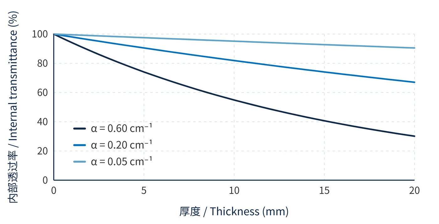
Fig. 2 makes the same point graphically: the larger the absorption coefficient, the steeper the marginal loss as thickness grows. That is why deep-UV systems lean toward thinner substrates while infrared windows get thicker for mechanical strength. The two applications pull material requirements in opposite directions.
If the choice is still open between quartz, ordinary glass and sapphire, compare hardness, thermal expansion and transmission range first, then narrow down to a grade — the trade-offs are set out in how to choose a substrate material.
Deep UV is JGS1 territory. Illumination for 193 nm lithography and excimer laser windows demand both short-wavelength transmission and material homogeneity, and the low metallic impurity of synthetic quartz is hard to substitute. 248 nm systems also favour JGS1, but absorption-driven heating deserves attention: a warming window changes both refractive index and surface figure.
UV inspection and fluorescence systems usually run on JGS2. For 365 nm excitation and 405 nm optics, JGS2 is sufficient and easier to cost-control. What matters in these systems is measured transmission at the working wavelength, not the grade label.
The low-OH advantage of JGS3 appears only in the near and short-wave infrared. At 850 nm and 1550 nm, the tail of the hydroxyl band can still produce measurable loss, and a low-OH material shrinks it; between 2.5 μm and 3.5 μm the difference is clear.
From a filter maker's perspective the substrate is the one layer that cannot be rescued later. A coating design can tune reflection and interference, but it cannot cancel absorption inside the glass. Choose the wrong material and every subsequent step optimises on a flawed foundation.
The first is treating a grade as a transmission guarantee. A quoted 185–2500 nm describes a typical usable window; absorption bands and ripple remain inside it, and transmission falls quickly near the endpoints.
The second is assuming lower hydroxyl is always better. Hydroxyl absorbs in the near infrared, so its influence on visible and deep-UV work is limited. Sacrificing the short-wavelength advantage of synthetic quartz to chase a low OH number is the wrong trade.
The third is expecting JGS3 to cover the whole infrared. It extends the long-wave limit to roughly 3.5 μm; beyond that, real transmission data decides, and mid- and far-infrared systems usually need silicon, germanium or zinc selenide instead.
The fourth is watching transmission alone. A filter substrate also has to satisfy dispersion, homogeneity, bubble and striae class, surface quality (60-40, 40-20 and finer), figure (λ/4, λ/10) and thickness tolerance. Any mismatch shows up in the finished part.
Finally, coating compatibility is often skipped. Deposition temperature, film stress and surface condition together govern adhesion and figure, and low-OH and synthetic quartz do not behave identically. Verify the coating process during sampling rather than after the order is released.
A grade only answers roughly where the material transmits. What decides whether a part works is measured transmission at the specified wavelength, the loss contributed by thickness, and whether surface and figure meet the system tolerance.
 365nm Narrow Bandpass Filter | Ø50mm | T>90%
OT-HBP3659050
365nm Narrow Bandpass Filter; FWHM 10nm; transmission >90%; blocking OD5; size Ø50mm; AOI 0°.
 450nm Narrow Bandpass Filter | Ø50mm
OT-HBP4509050
450nm Narrow Bandpass Filter; FWHM 10nm; transmission >90%; blocking OD5; size Ø50mm; AOI 0°.
 525nm Narrow Bandpass Filter | Ø50mm
OT-HBP5259050
525nm Narrow Bandpass Filter; FWHM 10nm; transmission >90%; blocking OD5; size Ø50mm; AOI 0°.
Send us your drawing and spectral targets — an engineer replies with a feasibility check and quotation within one business day.