Original content by the OOTEE Optics editorial team, drawn from first-hand production line and inspection data. Please credit the source when republishing.
Given limits in expertise and test conditions, the theories, parameters and conclusions here carry no guarantee of absolute accuracy. For technical learning and exchange only - never the sole basis for design, acceptance or selection. Corrections welcome.
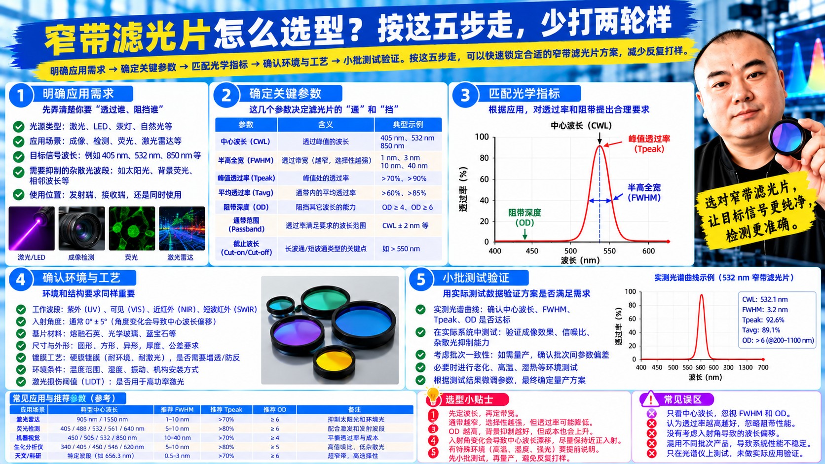
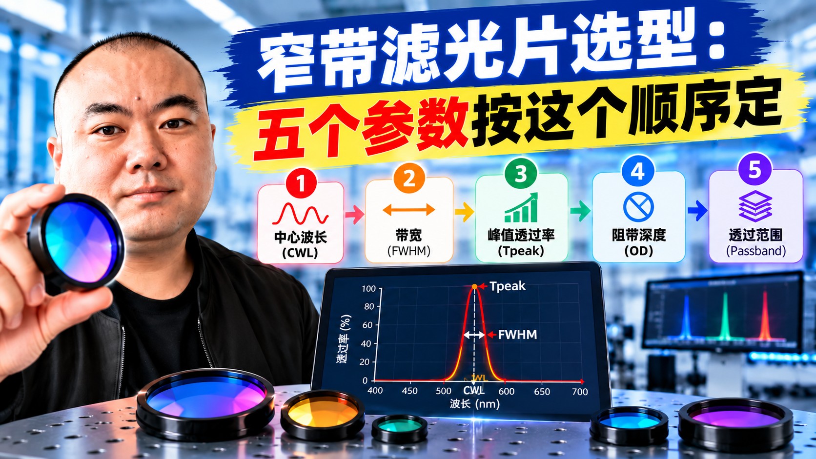
Narrowband filters are the most re-quoted item in our inbox — not because suppliers cannot coat them, but because the requirement itself has no priority order. Here is the sequence we actually use when aligning with customers.
Give a number, not a range, and say where it comes from: a fluorophore emission peak, a laser line, an absorption feature. State the tolerance too — ±2 nm is common, ±1 nm for demanding fluorescence work, and that one nanometre drives coating control and yield.
Signal scales with bandwidth, and so does background — but for a narrow signal against a continuum, narrowing the band suppresses background faster than it costs signal.
| FWHM | Typical use | Trade-off |
|---|---|---|
| 3–10 nm | Fluorescence imaging, Raman | Weak signal, needs more source power |
| 10–25 nm | PCR, flow cytometry, routine fluorescence | Best cost/performance compromise |
| 25–50 nm | Machine vision, colour separation | Limited background rejection |
OD is a log scale: OD3 is 0.1% transmission, OD6 is 0.0001%. "OD6" alone is not a specification — say OD6 from 200 to 900 nm, and state the excitation wavelength explicitly, because leaked excitation is usually the dominant background and needs an order of magnitude more rejection than ambient light.
Interference coatings shift blue at oblique incidence: about 1–2 nm at 10°, more than 8 nm at 25°. A converging f/2 beam reaches 15° at the margin, so the measured curve will always be wider and bluer than the catalogue. Either pre-compensate the CWL or collimate the beam.
Fill in a table with CWL, FWHM, peak transmission, blocking band and OD, AOI, dimensions and environmental requirements, and the "it came back unusable" conversation disappears.
 365nm Narrow Bandpass Filter | Ø50mm | T>90%
OT-HBP3659050
365nm Narrow Bandpass Filter; FWHM 10nm; transmission >90%; blocking OD5; size Ø50mm; AOI 0°.
 450nm Narrow Bandpass Filter | Ø50mm
OT-HBP4509050
450nm Narrow Bandpass Filter; FWHM 10nm; transmission >90%; blocking OD5; size Ø50mm; AOI 0°.
 525nm Narrow Bandpass Filter | Ø50mm
OT-HBP5259050
525nm Narrow Bandpass Filter; FWHM 10nm; transmission >90%; blocking OD5; size Ø50mm; AOI 0°.
Send us your drawing and spectral targets — an engineer replies with a feasibility check and quotation within one business day.



