Original content by the OOTEE Optics editorial team, drawn from first-hand production line and inspection data. Please credit the source when republishing.
Given limits in expertise and test conditions, the theories, parameters and conclusions here carry no guarantee of absolute accuracy. For technical learning and exchange only - never the sole basis for design, acceptance or selection. Corrections welcome.

Cleaning removes particles, fingerprints and residue while preserving the coating, substrate and assembly. It is a maintenance operation, not polishing. A few particles outside the clear aperture may justify leaving the surface alone; an oily fingerprint deserves prompt attention.
Disable the light source, let the optic cool and work in a clean area. Wear powder-free gloves and handle edges only. Record contamination locations and surface orientation before starting. Flaking, cracks, corrosion or adhesive seepage call for isolation and assessment rather than more rubbing.
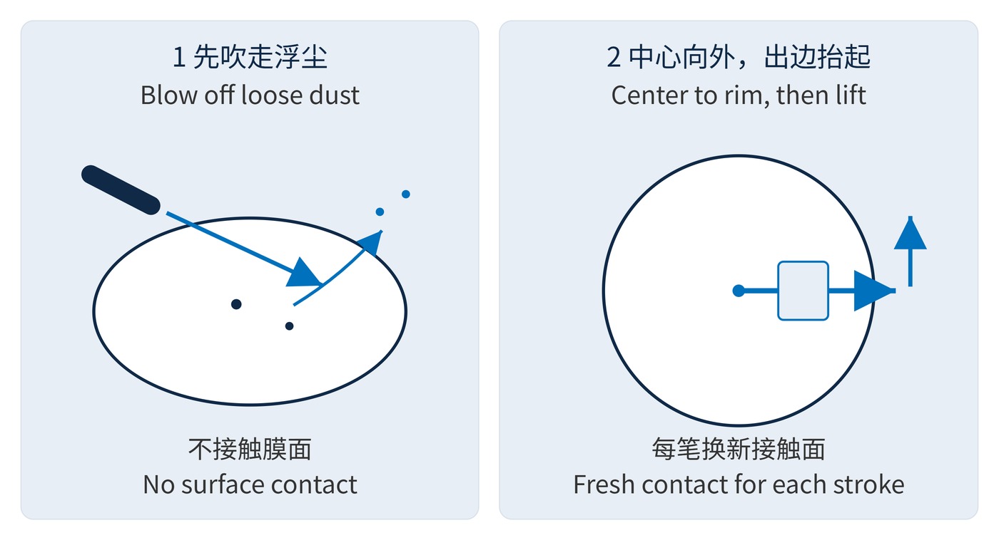
A trapped particle becomes an abrasive under a wipe. Organic residue can add absorption and scatter. Wet cleaning loosens contamination so a fresh wiping surface can remove it; dry friction and repeated strokes increase risk.
A useful throughput trend is the ratio measured at the same wavelength and beam aperture:
$$\eta_T(\lambda)=\frac{T_{\mathrm{after}}(\lambda)}{T_{\mathrm{before}}(\lambda)}$$
A value above 1 indicates improvement relative to the contaminated baseline, not proof of factory performance. Blocking requires a separate check of optical density (OD):
$$\mathrm{OD}(\lambda)=-\log_{10}T(\lambda)$$
Here $T$ is fractional transmittance. OD6 means $10^{-6}$, or 0.0001%. For an example filter with center wavelength (CWL) 780 nm, full width at half maximum (FWHM) 20 nm and OD6 blocking, retain the original angle of incidence (AOI) and polarization during verification. Higher passband transmission alone cannot establish intact blocking; the instrument needs adequate dynamic range.
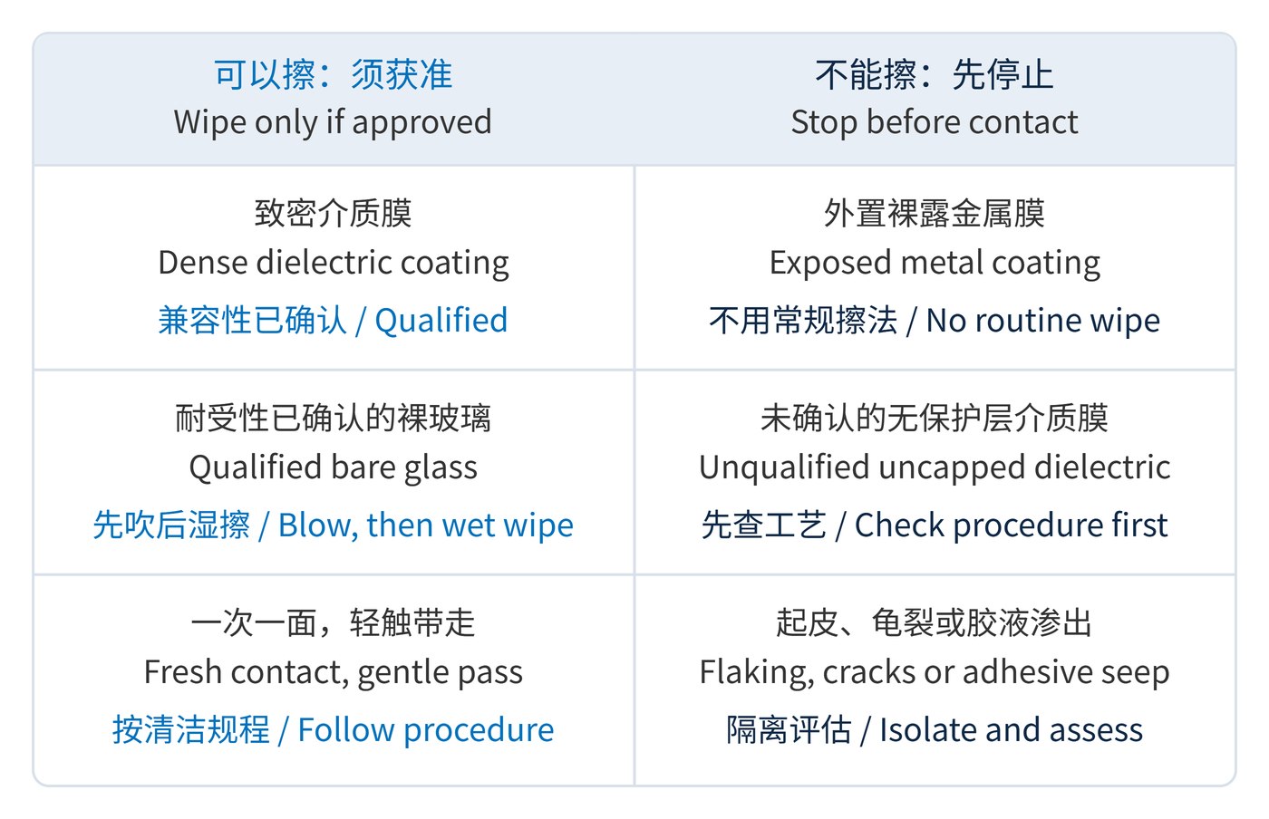
Fig. 1 separates qualified wet-wipe surfaces from surfaces that should remain untouched. Exposed metallic reflector coatings are excluded from routine contact cleaning. Protected metal also needs a specific procedure. An uncapped dielectric coating is not necessarily fragile, but unknown, porous, soft or degraded coatings must not be wiped without explicit qualification.
| Solvent | Suitable use | Limits |
|---|---|---|
| Anhydrous ethanol | Fingerprints and light oil on qualified glass and dense coatings; use low-residue optical or analytical grade | Do not substitute medical or denatured alcohol. Compatibility with metal, plastics and bonded assemblies is not assumed. Anhydrous does not mean residue-free. |
| Acetone | Some organic contamination on compatible inorganic coatings and bare glass | Can attack plastics, adhesives, paint and edge markings. Avoid unqualified assemblies and immersion of bonded filters. |
Purity does not establish compatibility. Check the component procedure and qualify a matching witness sample rather than testing an unknown optical surface. Both solvents are flammable: ventilate, exclude ignition sources and select gloves using solvent resistance data. Salts and water marks may require a separately approved aqueous process.
Check both faces independently: the front and rear may have different coatings, even on a single substrate. A solvent approved for one exposed face does not automatically qualify the rear face or its mounting materials. Keep the bottle closed between uses and dispense a small clean working quantity; do not return used liquid to the original container.
For machine vision filters, compare flat-field images and stray light under fixed illumination and exposure. Automatic exposure can hide a throughput change. Keep solvent and dissolved contamination out of retaining-ring gaps.
For Raman notch filters, check laser-line leakage and background as well as appearance. In high-power systems, residue can become a localized absorber. Complete the equipment acceptance procedure before restoring operating power.
For maintenance records, note the solvent grade, wipe type, affected face and inspection result. Comparing images under repeatable lighting helps distinguish persistent defects from changes caused by the viewing angle.
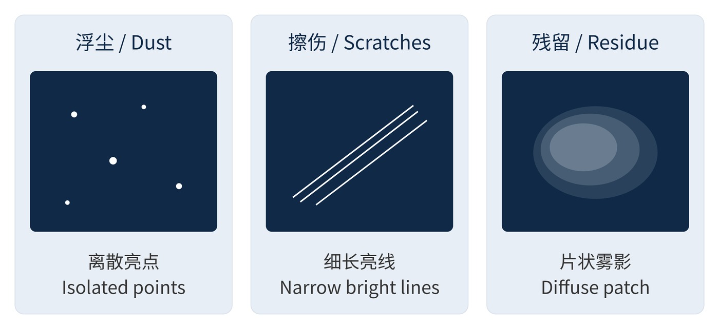
Use low-intensity visible light at an oblique angle against a dark background, viewing away from the specular reflection. In Fig. 3, dust appears as isolated bright points, scratches as narrow lines, arcs or parallel tracks, and residue as a diffuse patch. Changing illumination and optic orientation helps locate features but does not establish their identity.
Rubbing a suspected scratch can enlarge the damage. Confirm defects microscopically and grade them under the agreed inspection standard and conditions. A hard coating does not justify ordinary tissue, and strong solvent action does not prove assembly compatibility. Stop when contamination is controlled, no new defects are present and the original optical acceptance requirements are met.
 365nm Narrow Bandpass Filter | Ø50mm | T>90%
OT-HBP3659050
365nm Narrow Bandpass Filter; FWHM 10nm; transmission >90%; blocking OD5; size Ø50mm; AOI 0°.
 450nm Narrow Bandpass Filter | Ø50mm
OT-HBP4509050
450nm Narrow Bandpass Filter; FWHM 10nm; transmission >90%; blocking OD5; size Ø50mm; AOI 0°.
 525nm Narrow Bandpass Filter | Ø50mm
OT-HBP5259050
525nm Narrow Bandpass Filter; FWHM 10nm; transmission >90%; blocking OD5; size Ø50mm; AOI 0°.
Send us your drawing and spectral targets — an engineer replies with a feasibility check and quotation within one business day.