Original content by the OOTEE Optics editorial team, drawn from first-hand production line and inspection data. Please credit the source when republishing.
Given limits in expertise and test conditions, the theories, parameters and conclusions here carry no guarantee of absolute accuracy. For technical learning and exchange only - never the sole basis for design, acceptance or selection. Corrections welcome.
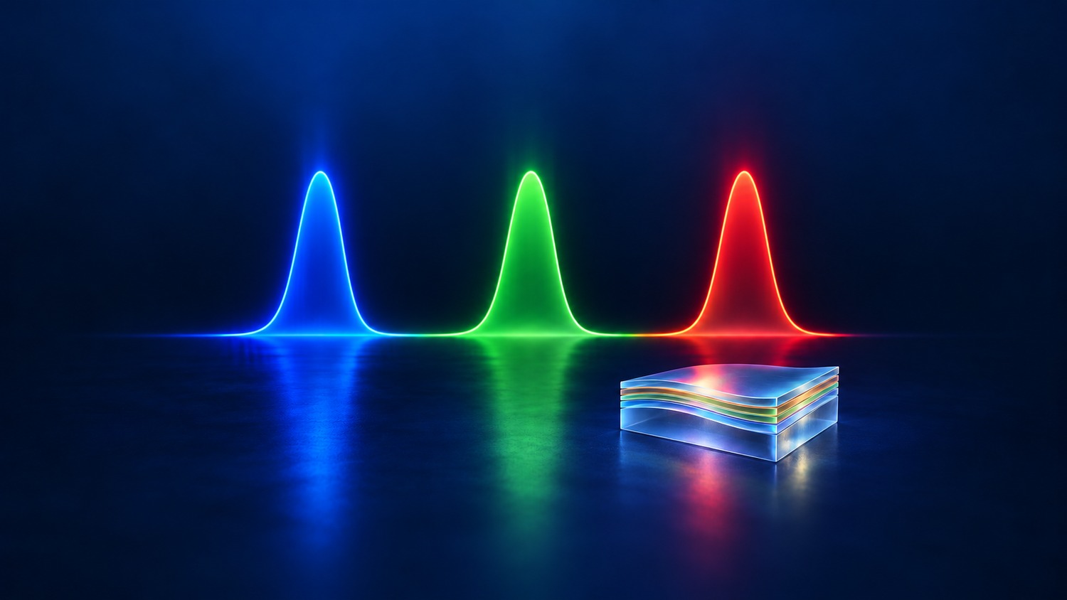
A multi-bandpass filter transmits two or more separated wavelength intervals, with blocking regions between them. Several useful bands can therefore share an optical path without admitting every wavelength between the shortest and longest target band. One element means one mounted optic; its functional coatings may occupy one or both substrate surfaces.
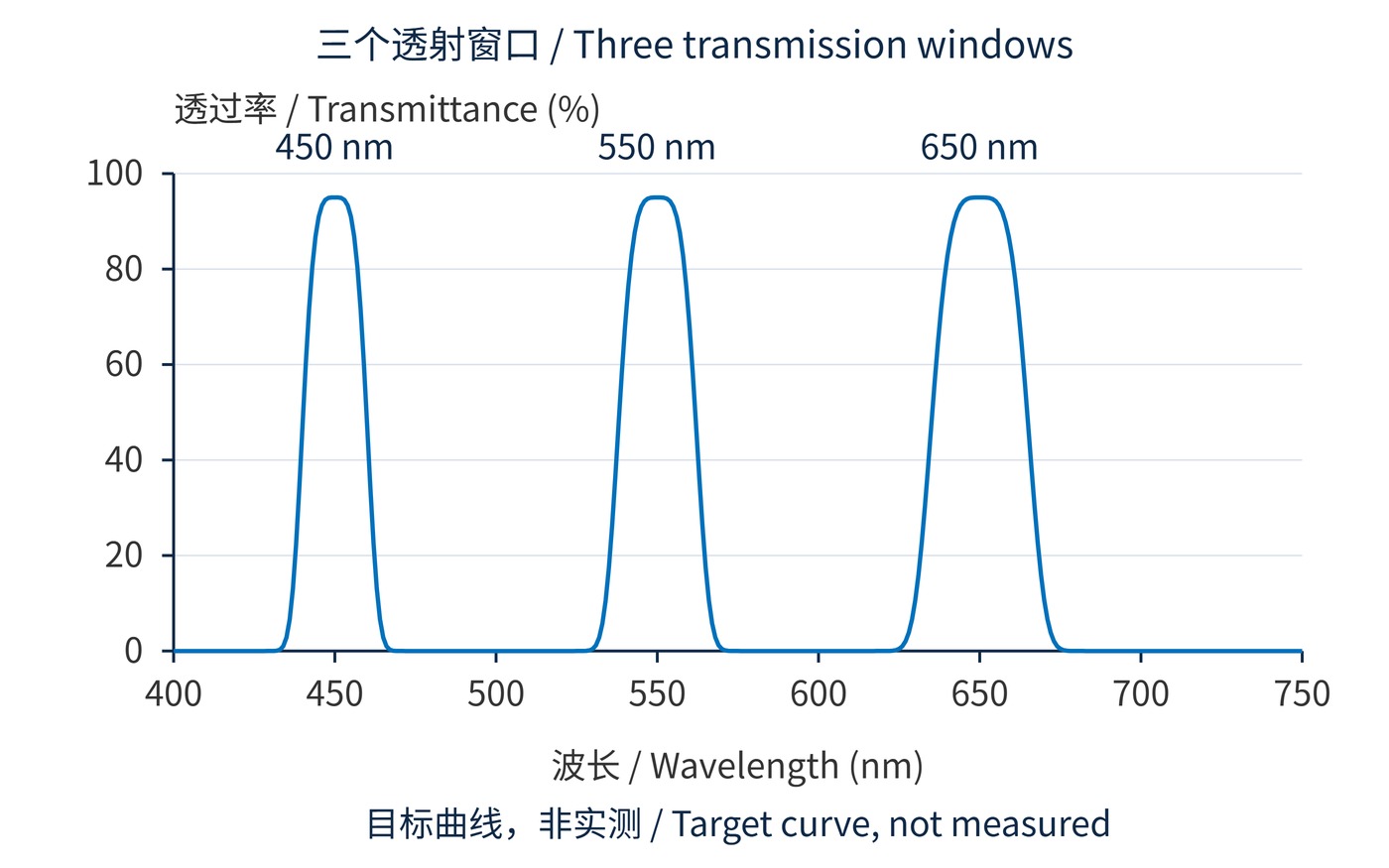
For example, a three-band requirement might specify center wavelengths (CWLs) of 450 nm, 550 nm and 650 nm, with full widths at half maximum (FWHMs) of 20 nm, 24 nm and 30 nm. Each window needs its own width, transmission requirement and tolerance. Calling this a “450–650 nm bandpass” would describe a very different function.
Dielectric coatings control transmission through interference among waves reflected at layer interfaces. A multiband design optimizes refractive indices and layer thicknesses across the full spectrum. It is not simply three independent coatings placed together: changing one region can alter ripple, edges or total coating thickness elsewhere.
Fig. 1 shows three independently defined windows on a common wavelength axis. The curve is sampled from an analytical target function. It illustrates spectral requirements, rather than a realizable layer prescription, a manufacturing capability or a measured filter.
Define the half-height crossings for each band separately. With ripple or asymmetric edges, agree on how the peak, crossings and center are identified.
$$T(\lambda_{i,1})=T(\lambda_{i,2})=\frac{T_{\mathrm{peak},i}}{2},\qquad \Delta\lambda_i=\lambda_{i,2}-\lambda_{i,1}$$
Optical density (OD) describes blocking using fractional transmittance. OD6 corresponds to 0.0001% transmission, not 0.000001%. The definition is documented in the NIST guide to spectral transmittance measurement.
$$\mathrm{OD}(\lambda)=-\log_{10}T(\lambda),\qquad T(\lambda)=\frac{I_{\mathrm{out}}(\lambda)}{I_{\mathrm{in}}(\lambda)}$$
Angle of incidence (AOI), beam cone and polarization are design inputs. Tilting an interference filter generally shifts its bands toward shorter wavelengths. Different bands need not shift or deform identically, so testing one peak does not qualify the complete optic.
Start with source spectra, useful signal spectra and detector response. Then specify intervals that must transmit and intervals that must block. The following is an illustrative requirement, not a product specification. Peak transmission alone cannot guarantee throughput across a working interval.
| Band | CWL / nm | FWHM / nm | Guaranteed interval / nm | Minimum transmission |
|---|---|---|---|---|
| 1 | 450 ± 2 | 20 ± 2 | 444–456 | ≥90% |
| 2 | 550 ± 2 | 24 ± 2 | 542–558 | ≥90% |
| 3 | 650 ± 2 | 30 ± 2 | 640–660 | ≥90% |
Separate blocking requirements could be OD≥6 over 400–425 nm, 480–520 nm, 585–615 nm and 690–750 nm. Leave the remaining intervals as transitions to be agreed. A boundary cannot simultaneously require 90% transmission and OD6. Fig. 1 does not validate the tolerances or blocking commitments in this separate example.
Complete the requirement with operating conditions, for example AOI 0°, beam half-cone angle ≤2°, temperature 20–30 °C and measurement positions within the clear aperture. Replace these illustrative conditions with the actual beam geometry and polarization before qualification.
Allocate tolerances across source drift, filter variation and mounting angle. The guaranteed transmission interval should still contain the useful signal after those changes, while blocking intervals should cover moving interference lines. Simply widening every passband consumes the space available for interband rejection. Check the worst combination of source and filter shifts, rather than treating each nominal spectrum as fixed. If the resulting margins disappear, revise the band allocation or optical architecture before specifying tighter coating tolerances.
Request spectral data across the detector's sensitive range, together with wavelength accuracy, instrument spectral bandwidth and the stray-light floor. A trace reaching an OD4 measurement floor cannot establish OD6. Inspect narrow leakage peaks as well as the nominal blocking intervals; a few isolated samples may miss them.
Multicolor fluorescence systems can share one emission filter across several windows, reducing filter changes. However, excitation light entering any open window can reach the detector. Excitation filtering, wavelength routing and emission filtering must therefore be checked together.
In machine vision, different illumination wavelengths can be switched sequentially while retaining the same lens and detector. Multiwavelength photometry can also share an optic, provided source modulation, downstream spectral separation or separate detectors establish which band produced each reading.
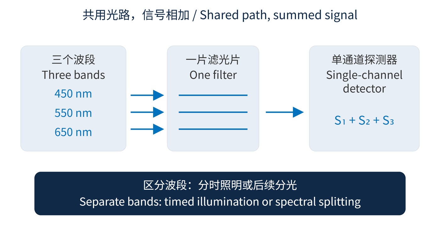
As Fig. 2 illustrates, a broadband single-channel detector adds the contributions from all open bands. Spectral selection by the filter does not create three independent electrical measurements.
Can three single-band filters in series make a three-band filter? Neglecting multiple reflections, their transmittances multiply. The surviving spectrum is their overlap. Three nonoverlapping single-band filters usually transmit very little in series; they do not produce the union of their windows.
$$T_{\mathrm{series}}(\lambda)\approx\prod_{j=1}^{N}T_j(\lambda)$$
Do more peaks guarantee more information? Additional windows can also admit more background. Without channel discrimination, the result remains a mixed signal. Are three peak measurements sufficient? Qualification must also cover minimum in-band transmission, edge positions, interband leakage and operating angles. A complete requirement connects every transmission window and blocking interval to a defined method of reading the signal.
 365nm Narrow Bandpass Filter | Ø50mm | T>90%
OT-HBP3659050
365nm Narrow Bandpass Filter; FWHM 10nm; transmission >90%; blocking OD5; size Ø50mm; AOI 0°.
 450nm Narrow Bandpass Filter | Ø50mm
OT-HBP4509050
450nm Narrow Bandpass Filter; FWHM 10nm; transmission >90%; blocking OD5; size Ø50mm; AOI 0°.
 525nm Narrow Bandpass Filter | Ø50mm
OT-HBP5259050
525nm Narrow Bandpass Filter; FWHM 10nm; transmission >90%; blocking OD5; size Ø50mm; AOI 0°.
Send us your drawing and spectral targets — an engineer replies with a feasibility check and quotation within one business day.