Original content by the OOTEE Optics editorial team, drawn from first-hand production line and inspection data. Please credit the source when republishing.
Given limits in expertise and test conditions, the theories, parameters and conclusions here carry no guarantee of absolute accuracy. For technical learning and exchange only - never the sole basis for design, acceptance or selection. Corrections welcome.
A 1 nm, 10 nm or 50 nm bandwidth describes a spectral window, not a quality grade. Center wavelength (CWL) locates that window. Full width at half maximum (FWHM) measures its width at half the peak transmission; it is a full width, not a half width.
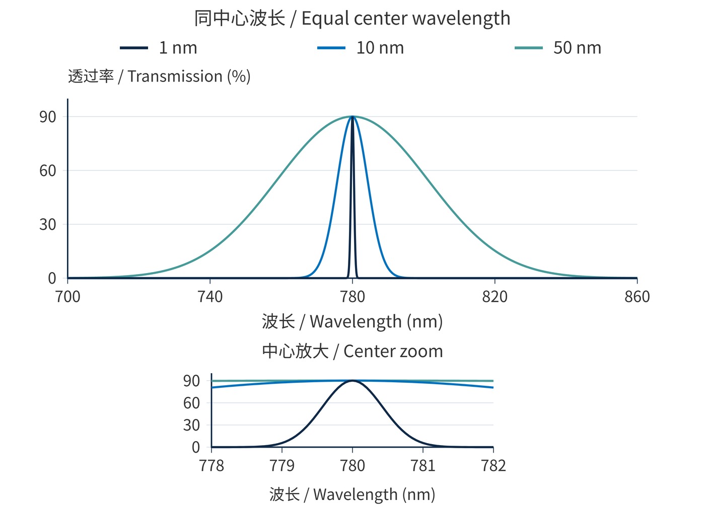
At a common CWL of 780 nm, a 1 nm window favors rejection close to a narrow target line. A 10 nm window offers more room for wavelength variation. A 50 nm window can collect a broader emission band. The useful distinction is how each window overlaps the signal throughout operation.
Figure 1 compares Gaussian transmission models with the same CWL and 90% peak transmission. Only FWHM changes. The half-height definition is:
$$T(\lambda_1)=T(\lambda_2)=\frac{T_{\mathrm{peak}}}{2},\qquad \mathrm{FWHM}=\lambda_2-\lambda_1$$
For signal spectral power density $s(\lambda)$, transmitted signal power is determined by the overlap integral:
$$P_{\mathrm{s}}=\int s(\lambda)T(\lambda)\,\mathrm{d}\lambda$$
With flat background and nearly constant detector response, background power scales approximately with bandwidth for a fixed filter shape. The model areas have a 1:10:50 ratio. A broadband signal may gain similarly; a narrow laser line already fully transmitted will not. If background shot noise dominates and signal stays constant, signal-to-noise ratio scales approximately as the inverse square root of bandwidth. This shortcut does not apply to a read-noise-limited detector.
Optical density (OD) specifies blocking, while angle of incidence (AOI) affects passband position. Equal FWHM does not imply equal blocking range, shape or minimum transmission. State temperature, AOI, cone angle and polarization with the spectral requirements.
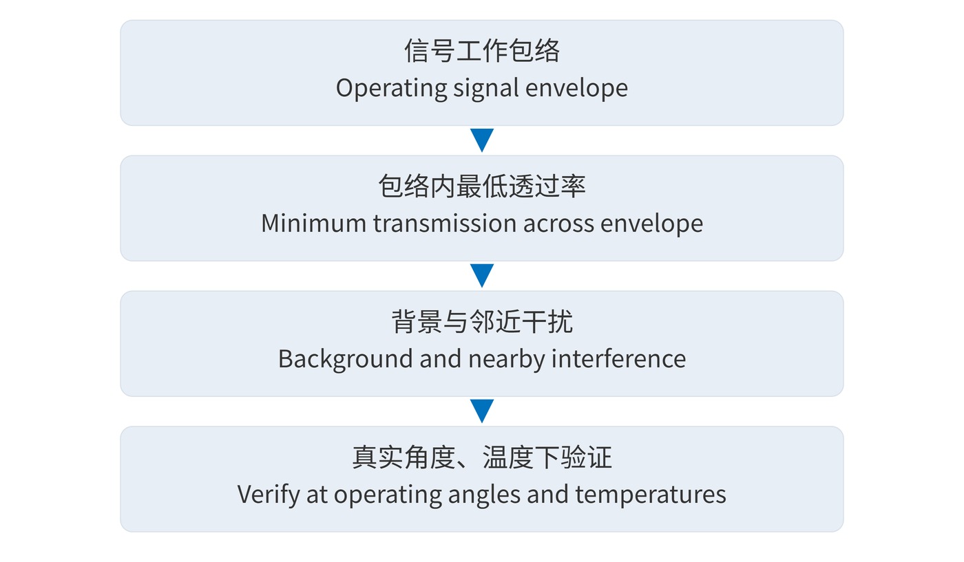
Build a wavelength envelope covering source linewidth, source tolerance and drift, plus filter centering tolerance and angular shift. Require minimum transmission across that envelope. Merely fitting inside the half-height edges is insufficient. Figure 2 shows the sequence.
For example, a requirement of at least 85% transmission from 779 to 781 nm cannot be met simply by specifying CWL 780 nm and FWHM 1 nm. Its half-height edges lie inside the required interval. A 10 nm design is a candidate, but interference at 784 nm could make widening unacceptable. Source stability or the angular budget may need improvement.
An illustrative request could specify CWL 780 nm, FWHM 10 nm, transmission ≥85% over 779–781 nm, OD≥6 over 400–770 nm and 790–1100 nm, AOI 0°, and operation at 20–30 °C. Add tolerances and cone angle; these are discussion targets, not a stock-product guarantee. When comparing narrow bandpass filters, request full curves and guaranteed performance under the intended conditions.
Keep clear aperture and measurement position consistent when comparing samples. For weak-light measurements, record the signal and background regions at the same exposure time. This distinguishes useful collection gain from increased unwanted flux. Also check whether the wider window consumes detector headroom: a brighter image can force a shorter exposure without improving detection. If performance changes across the field, examine the angular distribution before assigning the difference to nominal bandwidth.
| Bandwidth | Starting application | Critical check |
|---|---|---|
| 1 nm | Stable narrow-line reception; nearby-line separation | Source drift, filter tolerance and ray angles |
| 10 nm | Laser reception with drift; narrow-spectrum active lighting | Signal coverage versus nearby interference |
| 50 nm | Broad fluorescence collection; LED-band imaging | Spectral overlap, excitation leakage and saturation |
A 1 nm filter can reject strong background around a narrow signal, provided alignment and wavelength stability support it. Prefer a collimated beam: converging or wide-field rays encounter different AOIs. A 10 nm filter tolerates a larger wavelength envelope, but still needs application-specific verification.
A 50 nm band can recover more broadband emission. In fluorescence channels, neighboring spectra may instead demand a narrower window to control crosstalk. For machine vision filters, consider illumination, camera response and transmission across the entire field together.
Narrower does not automatically mean better contrast after signal loss. Wider does not automatically improve signal-to-noise ratio. Expanding from 10 nm to 50 nm around an already captured laser line may add mainly background; reducing a broadband signal to 1 nm may discard most useful light.
FWHM is neither a guaranteed high-transmission interval nor a blocking specification. Allow separate transition regions. Measuring a 1 nm peak also requires sufficiently fine instrument spectral bandwidth and sampling to avoid an artificially broadened, lowered peak. Make the final comparison using the actual signal spectrum, angles, temperature and exposure margin.
 365nm Narrow Bandpass Filter | Ø50mm | T>90%
OT-HBP3659050
365nm Narrow Bandpass Filter; FWHM 10nm; transmission >90%; blocking OD5; size Ø50mm; AOI 0°.
 450nm Narrow Bandpass Filter | Ø50mm
OT-HBP4509050
450nm Narrow Bandpass Filter; FWHM 10nm; transmission >90%; blocking OD5; size Ø50mm; AOI 0°.
 525nm Narrow Bandpass Filter | Ø50mm
OT-HBP5259050
525nm Narrow Bandpass Filter; FWHM 10nm; transmission >90%; blocking OD5; size Ø50mm; AOI 0°.
Send us your drawing and spectral targets — an engineer replies with a feasibility check and quotation within one business day.



