Original content by the OOTEE Optics editorial team, drawn from first-hand production line and inspection data. Please credit the source when republishing.
Given limits in expertise and test conditions, the theories, parameters and conclusions here carry no guarantee of absolute accuracy. For technical learning and exchange only - never the sole basis for design, acceptance or selection. Corrections welcome.

A filter is backwards when light reaches the opposite surface from the one specified in its assembly drawing. Exchanging the two faces while preserving the optical plane is different from rotating the entire optic into a new tilt. The first changes which layers light encounters first; the second can also redirect the reflected beam.
Uniform absorbing glass with identical surface treatments, or a fully symmetric structure in matching surroundings, usually works equally well either way. An asymmetric coating does not automatically lose transmission performance in reverse. For a linear reciprocal optic, corresponding forward and reverse modes have equal power transmission when both external media are the same.
At a given wavelength and for corresponding polarization modes, reciprocity gives:
$$T_{1\rightarrow2}(\lambda)=T_{2\rightarrow1}(\lambda)$$
This does not require equal reflection from both sides of an absorbing assembly. For either direction, transmittance $T$, reflectance $R$ and absorptance $A$ obey:
$$T+R+A=1$$
In a lossless reciprocal structure under these conditions, power reflectance is also equal. Reflection phase and the location of the reflecting surface can still differ. With absorbing layers, illumination from opposite sides can redistribute reflection and absorption. Rejected light entering absorbing material first may increase heating or fluorescence without increasing direct transmission.
Fig. 1 compares illumination from opposite sides of the same tilted dichroic. Transmission continues forward; reflection returns into the incident half-space. The laboratory output ports change sides. This exchanges the spatial branches, not the wavelength bands assigned to transmission and reflection. Simply exchanging faces within an unchanged optical plane does not reverse the main reflection direction.
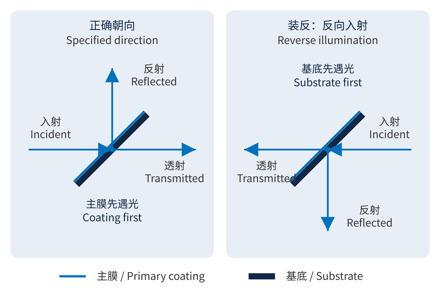
With the main coating facing the source, rejected light can reflect before crossing the substrate. Reverse illumination may send it through the substrate first. Weak rear-surface reflections can then produce displaced ghosts, depending on thickness, tilt and the receiving aperture.
Optical density (OD) is defined by:
$$\mathrm{OD}(\lambda)=-\log_{10}T(\lambda)$$
OD6 means $T=10^{-6}$, or 0.0001%. A higher background after reversal can reduce the system’s apparent blocking depth. Fluorescence or additional reflected light reaching the detector may explain that result; it does not establish a failure of reciprocity. State whether the measurement isolates direct transmission or includes background.
Consider a narrow bandpass filter with center wavelength (CWL) 780 nm, full width at half maximum (FWHM) 20 nm and OD6 blocking. The blocking interval, polarization, beam cone and angle of incidence (AOI) are also required. AOI is measured from the surface normal. A comparison at 0° cannot verify performance specified at 45°.
| Construction or marking | Assembly check | What to compare after reversal |
|---|---|---|
| Symmetric construction | Match external media and surface treatments | Direct transmission should remain comparable |
| Dichroic or face-specified bandpass | Identify the primary coating and source side | Reflection port, ghosts and background |
| Assembly with absorbing layers | Confirm layer order and optical power | Heating, fluorescence and return reflections |
| Dot, bevel or model engraving | Relate the mark to a numbered face | A mark alone does not define incidence |
An arrow may indicate propagation or point toward the surface that should face the source. Dots can identify a coated face; bevels and engraving can serve as assembly references. These conventions are not universal. Use the drawing and the marking definition supplied for that batch rather than assuming every arrow follows the beam.
In fluorescence detection, strong excitation accompanies a weak desired signal. A reversed face-specified filter may raise the blank-sample background while leaving the useful passband signal nearly unchanged. Record the dark signal, blank and target separately before attributing the change to transmission loss.
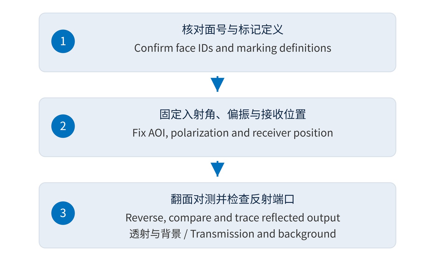
For beam combining or splitting with a dichroic mirror, verify the reflected detector port first. In imaging, inspect bright points for secondary images. Following Fig. 2, stop illumination, record the original orientation and compare both faces at unchanged AOI, polarization, power and receiver position. Trace the reflected beam as well as measuring the transmitted channel.
 365nm Narrow Bandpass Filter | Ø50mm | T>90%
OT-HBP3659050
365nm Narrow Bandpass Filter; FWHM 10nm; transmission >90%; blocking OD5; size Ø50mm; AOI 0°.
 450nm Narrow Bandpass Filter | Ø50mm
OT-HBP4509050
450nm Narrow Bandpass Filter; FWHM 10nm; transmission >90%; blocking OD5; size Ø50mm; AOI 0°.
 525nm Narrow Bandpass Filter | Ø50mm
OT-HBP5259050
525nm Narrow Bandpass Filter; FWHM 10nm; transmission >90%; blocking OD5; size Ø50mm; AOI 0°.
Send us your drawing and spectral targets — an engineer replies with a feasibility check and quotation within one business day.