Original content by the OOTEE Optics editorial team, drawn from first-hand production line and inspection data. Please credit the source when republishing.
Given limits in expertise and test conditions, the theories, parameters and conclusions here carry no guarantee of absolute accuracy. For technical learning and exchange only - never the sole basis for design, acceptance or selection. Corrections welcome.
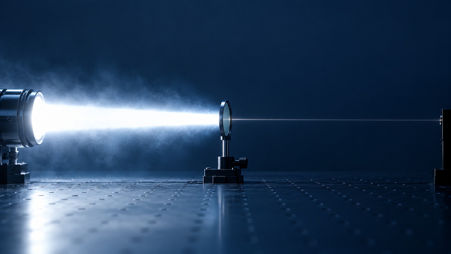
Blocking range defines the wavelengths to be rejected. Optical density (OD) quantifies the rejection at each wavelength. Neither is a complete specification alone: “400–1100 nm blocking” leaves the leakage limit open, while “OD6” says nothing about where that limit applies.
A bandpass filter normally has separate blocking intervals on either side of its useful transmission band. Center wavelength (CWL) and full width at half maximum (FWHM) characterize the selected signal, but do not establish the blocking boundaries. The useful question is which wavelengths meet a stated minimum OD under stated operating conditions.
Use the power transmission ratio at the same wavelength, expressed as a fraction rather than a percentage. OD is dimensionless. Rejection may involve reflection or absorption, so OD alone does not describe heating.
$$T(\lambda)=\frac{P_{\mathrm{out}}(\lambda)}{P_{\mathrm{in}}(\lambda)},\qquad \mathrm{OD}(\lambda)=-\log_{10}T(\lambda)$$
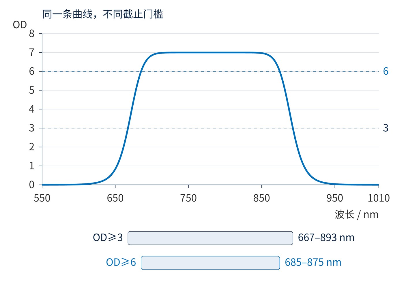
OD6 means 0.0001% transmission. A filter reaching OD7 at one wavelength does not necessarily maintain OD6 throughout its blocking band. Fig. 1 applies two thresholds to one calculated curve: the higher threshold produces a narrower qualifying interval. This analytical illustration is neither a coating simulation nor measured product data.
For a specified interval $B$ and required depth $D$, pointwise compliance has a precise meaning:
$$\min_{\lambda\in B}\mathrm{OD}(\lambda)\ge D\quad\Longleftrightarrow\quad\max_{\lambda\in B}T(\lambda)\le10^{-D}$$
The weakest rejection point controls acceptance. An average OD can conceal a narrow leakage feature. Angle of incidence (AOI), polarization, cone angle and temperature also matter: boundaries measured with a collimated beam at normal incidence cannot simply be carried over to a tilted or converging beam.
Start with the overlap between source emission and detector sensitivity, excluding the desired signal band. Identify broad background regions and strong individual lines separately. A laser interferer needs a requirement covering its wavelength drift as well as its nominal wavelength. Allow explicit transition regions between useful transmission and deep blocking.
For discussion, consider CWL 780 nm, FWHM 20 nm, transmission of at least 85% across 770–790 nm, and pointwise OD≥6 over 400–750 nm and 810–1100 nm. Conditions are AOI 0°, collimated unpolarized light and 23 °C. The remaining 750–770 nm and 790–810 nm intervals are transitions requiring separate edge criteria. These are illustrative design targets; their combined feasibility needs assessment.
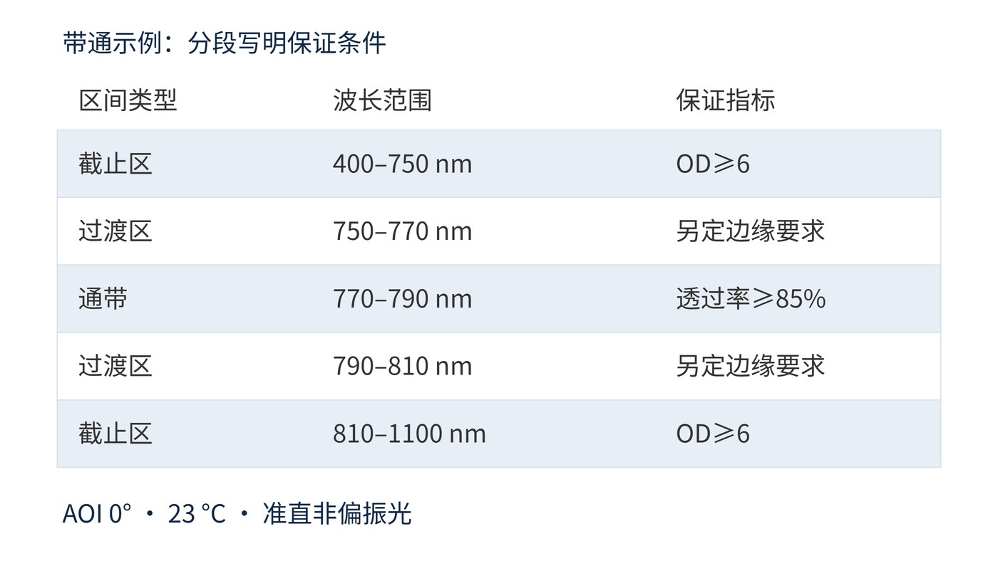
As Fig. 2 shows, a blanket “OD6 from 400 to 1100 nm” would contradict a transmitting band at 780 nm. Specify each interval and agree on wavelength sampling, instrument spectral bandwidth, clear aperture and measurement uncertainty. A measurement limited by stray light to OD4 cannot establish OD6 compliance.
Also agree whether endpoints are included and how wavelength uncertainty is handled. Leave margin for a background line near an edge. Unmeasured regions cannot inherit an OD guarantee by extrapolation. Leakage around the filter mount requires separate control.
Weak fluorescence detection needs rejection of the excitation line and other background reaching the sensor. A vision system illuminated at 780 nm can still collect visible and near-infrared ambient light. A laser receiver may need both broad background rejection and a separate minimum OD near a strong interfering line.
The relevant system quantity weights leakage by background spectral power density $S(\lambda)$ and detector responsivity $R(\lambda)$. With responsivity in A/W, integrating over the unwanted interval set $B$ gives background photocurrent:
$$I_{\mathrm{bg}}=\int_B S(\lambda)T(\lambda)R(\lambda)\,\mathrm{d}\lambda$$
Extending blocking into wavelengths carrying negligible weighted background may provide little benefit. Conversely, a small leakage feature coinciding with a strong source line can dominate the result.
A verifiable blocking requirement combines a minimum OD, explicit wavelength intervals, operating conditions and a measurement method. Acceptance should follow the weakest spectral point and the system background budget.
Definition reference: RP Photonics: Optical Density.
 365nm Narrow Bandpass Filter | Ø50mm | T>90%
OT-HBP3659050
365nm Narrow Bandpass Filter; FWHM 10nm; transmission >90%; blocking OD5; size Ø50mm; AOI 0°.
 450nm Narrow Bandpass Filter | Ø50mm
OT-HBP4509050
450nm Narrow Bandpass Filter; FWHM 10nm; transmission >90%; blocking OD5; size Ø50mm; AOI 0°.
 525nm Narrow Bandpass Filter | Ø50mm
OT-HBP5259050
525nm Narrow Bandpass Filter; FWHM 10nm; transmission >90%; blocking OD5; size Ø50mm; AOI 0°.
Send us your drawing and spectral targets — an engineer replies with a feasibility check and quotation within one business day.



