Original content by the OOTEE Optics editorial team, drawn from first-hand production line and inspection data. Please credit the source when republishing.
Given limits in expertise and test conditions, the theories, parameters and conclusions here carry no guarantee of absolute accuracy. For technical learning and exchange only - never the sole basis for design, acceptance or selection. Corrections welcome.
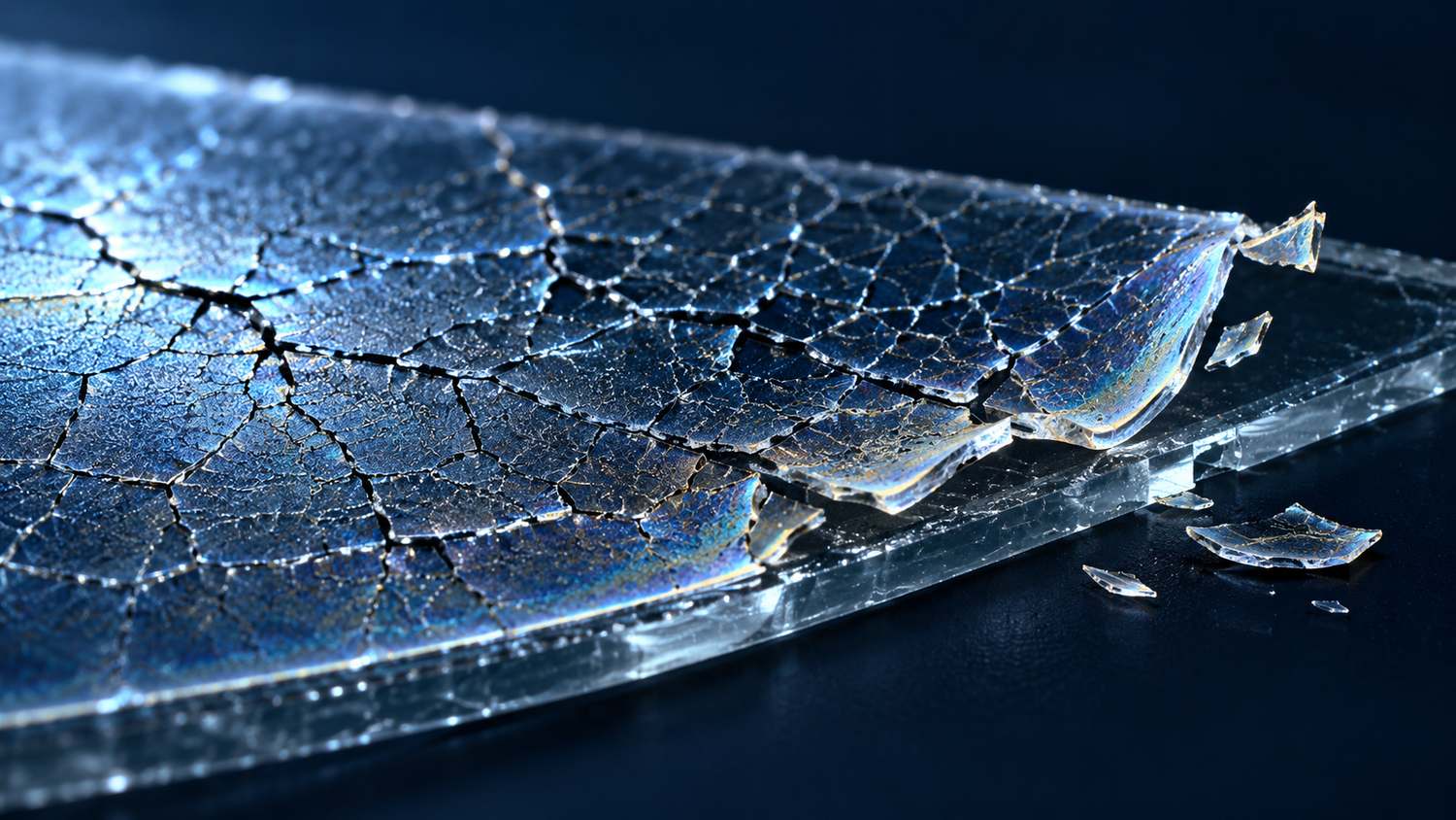
A deposited coating can retain mechanical stress after it reaches room temperature. The film would contract or expand if it were free, but the substrate and neighboring layers restrain it. Crazing describes a network of fine cracks in the coating; it is distinct from an isolated cleaning scratch and does not necessarily mean the glass has fractured.
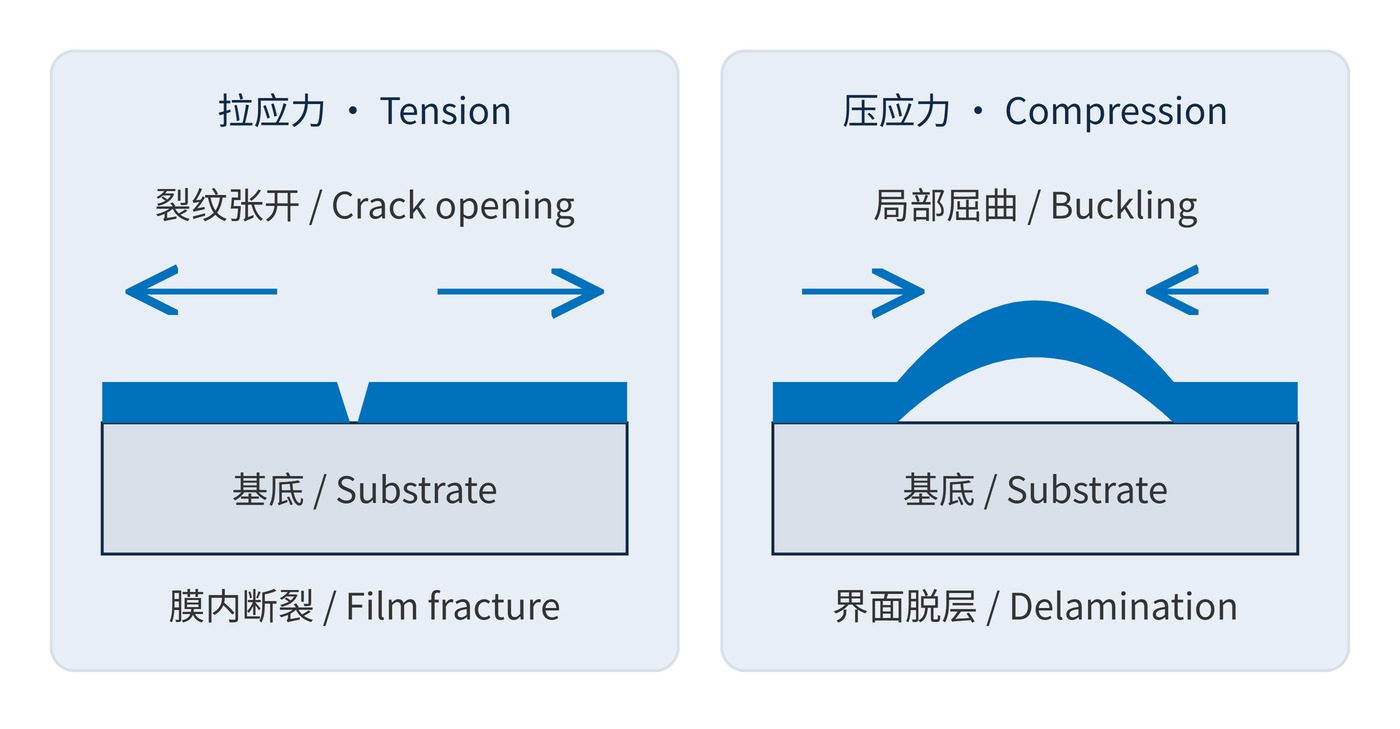
Tension promotes crack opening. Compression can buckle a locally detached film and drive further delamination. These mechanisms can coexist, as illustrated in Fig. 1, so surface appearance alone cannot establish the stress sign. Cracks increase scattering, while missing coating can create localized leakage before a large change appears in aperture-averaged transmission.
Residual stress combines intrinsic growth stress with thermal mismatch. Particle energy, evolving microstructure, deposition temperature, and subsequent treatment all matter. A process name alone does not determine the sign. Adsorption and structural relaxation can also change stress during storage.
For an elastic, uniform single film constrained by a much thicker substrate, a temperature change gives the approximate in-plane stress increment:
$$\Delta\sigma_{\mathrm{th}}\approx\frac{E_{\mathrm{f}}}{1-\nu_{\mathrm{f}}}(\alpha_{\mathrm{s}}-\alpha_{\mathrm{f}})\Delta T$$
Tension is positive. Here $E$ is Young's modulus, $\nu$ is Poisson's ratio, and $\alpha$ is thermal expansion coefficient; subscripts f and s identify film and substrate. A film with greater expansion coefficient develops a tensile increment on cooling. A multilayer stack requires a more complete treatment of layer interactions.
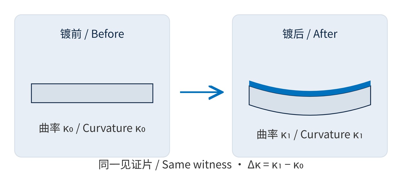
Fig. 2 shows curvature measurements on a same-run witness. The magnitude form of the Stoney relation estimates the average film stress:
$$|\bar{\sigma}_{\mathrm{f}}|\approx\frac{E_{\mathrm{s}}t_{\mathrm{s}}^2}{6(1-\nu_{\mathrm{s}})t_{\mathrm{f}}}|\Delta\kappa|$$
The thicknesses are $t_{\mathrm{s}}$ and total coating thickness $t_{\mathrm{f}}$; $\Delta\kappa$ is the curvature change. Determine stress sign separately using a defined curvature convention. The approximation assumes a thin film, small deformation, and nearly uniform biaxial stress. Cracked films, double-sided coatings, and strongly nonuniform specimens need other analysis.
Using $E_{\mathrm{s}}=72\,\mathrm{GPa}$, $\nu_{\mathrm{s}}=0.17$, $t_{\mathrm{s}}=1\,\mathrm{mm}$, $t_{\mathrm{f}}=5\,\mathrm{\mu m}$, and $|\Delta\kappa|=0.02\,\mathrm{m}^{-1}$ gives approximately $58\,\mathrm{MPa}$. This is an arithmetic example, not a pass limit. Fracture also depends on thickness, flaws, toughness, and interface adhesion. A low stack average can conceal highly stressed individual layers.
Define the substrate, thickness, clear aperture, mounting arrangement, and thermal history alongside the spectral requirement. An illustrative target is center wavelength (CWL) 780 nm, full width at half maximum (FWHM) 20 nm, angle of incidence (AOI) 0°, and optical density (OD) of at least 6 over 400–700 nm. Spectral compliance alone does not establish mechanical reliability.
| Check | Agree before testing |
|---|---|
| Appearance | Crack, blister, and delamination criteria; illumination, magnification, and edge exclusion |
| Stress and figure | Witness material and thickness, coating thickness, curvature method, and finished-part figure limits |
| Environment and mounting | Temperature endpoints, ramp rate, dwell, cycle count, and mounting preload |
| Optical retest | Passband, blocking, and scatter at matched locations and apertures; instrument detection floor |
A discussion example is −20 to 80 °C at 2 °C/min, with 30 min endpoint dwells and 20 cycles. Start each dwell after specimen temperature stabilizes. Adapt the protocol to thermal inertia and service life; it is not a universal filter rating. Confirm sufficient instrument dynamic range before accepting an OD6 retest.
Keep inspection conditions identical before and after exposure. Photograph the same locations and distinguish new damage from pre-existing defects. A witness is useful for tracking a deposition run, but its curvature cannot certify a finished filter with a different substrate thickness or mounting load. Acceptance should therefore include the actual part geometry and the relevant assembly condition.
Thick stacks on thin substrates warrant particular attention to figure change in narrowband imaging. High-rejection fluorescence systems are sensitive to localized leakage through cracks or pinholes. Outdoor sensors undergoing repeated thermal cycles should be evaluated in a representative mount as well as on free witnesses.
Follow the evidence sequence in Fig. 3. Cracks repeatedly starting at clamp locations suggest an assembly-load investigation. Abnormal same-run witness curvature warrants reviewing deposition and cooling records. Edge-only lifting calls for checks of contamination, bevel damage, and coating termination. Preserve an uncleaned failed sample so wiping does not erase evidence.
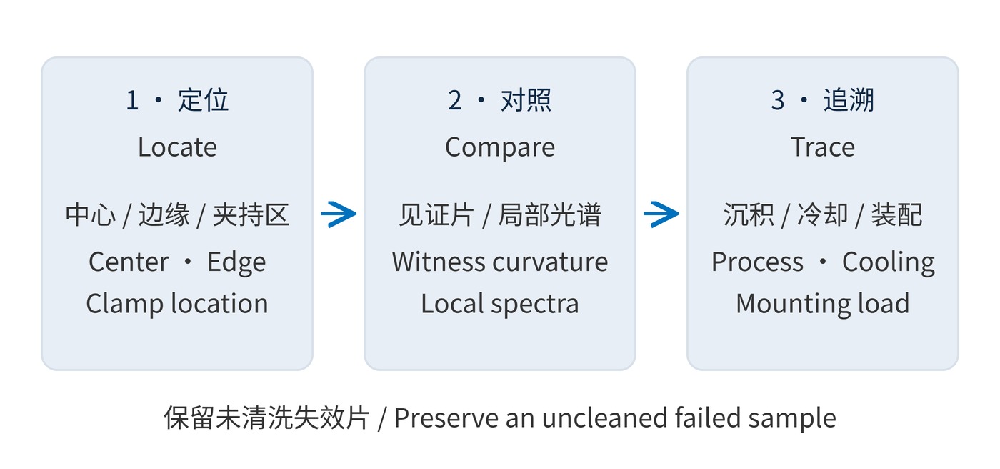
Connect microscopy, curvature records, and optical measurements at matching positions. No visible crazing means no cracks were found under the stated inspection conditions; reliability still requires retesting after the agreed environmental exposure.
Technical references: the PMC-indexed study "Internal Stress Prediction and Measurement of Mid-Infrared Multilayer Thin Films", and the paper in the International Journal of Fracture on interaction between cracking, delamination and buckling in brittle elastic thin films.
 365nm Narrow Bandpass Filter | Ø50mm | T>90%
OT-HBP3659050
365nm Narrow Bandpass Filter; FWHM 10nm; transmission >90%; blocking OD5; size Ø50mm; AOI 0°.
 450nm Narrow Bandpass Filter | Ø50mm
OT-HBP4509050
450nm Narrow Bandpass Filter; FWHM 10nm; transmission >90%; blocking OD5; size Ø50mm; AOI 0°.
 525nm Narrow Bandpass Filter | Ø50mm
OT-HBP5259050
525nm Narrow Bandpass Filter; FWHM 10nm; transmission >90%; blocking OD5; size Ø50mm; AOI 0°.
Send us your drawing and spectral targets — an engineer replies with a feasibility check and quotation within one business day.