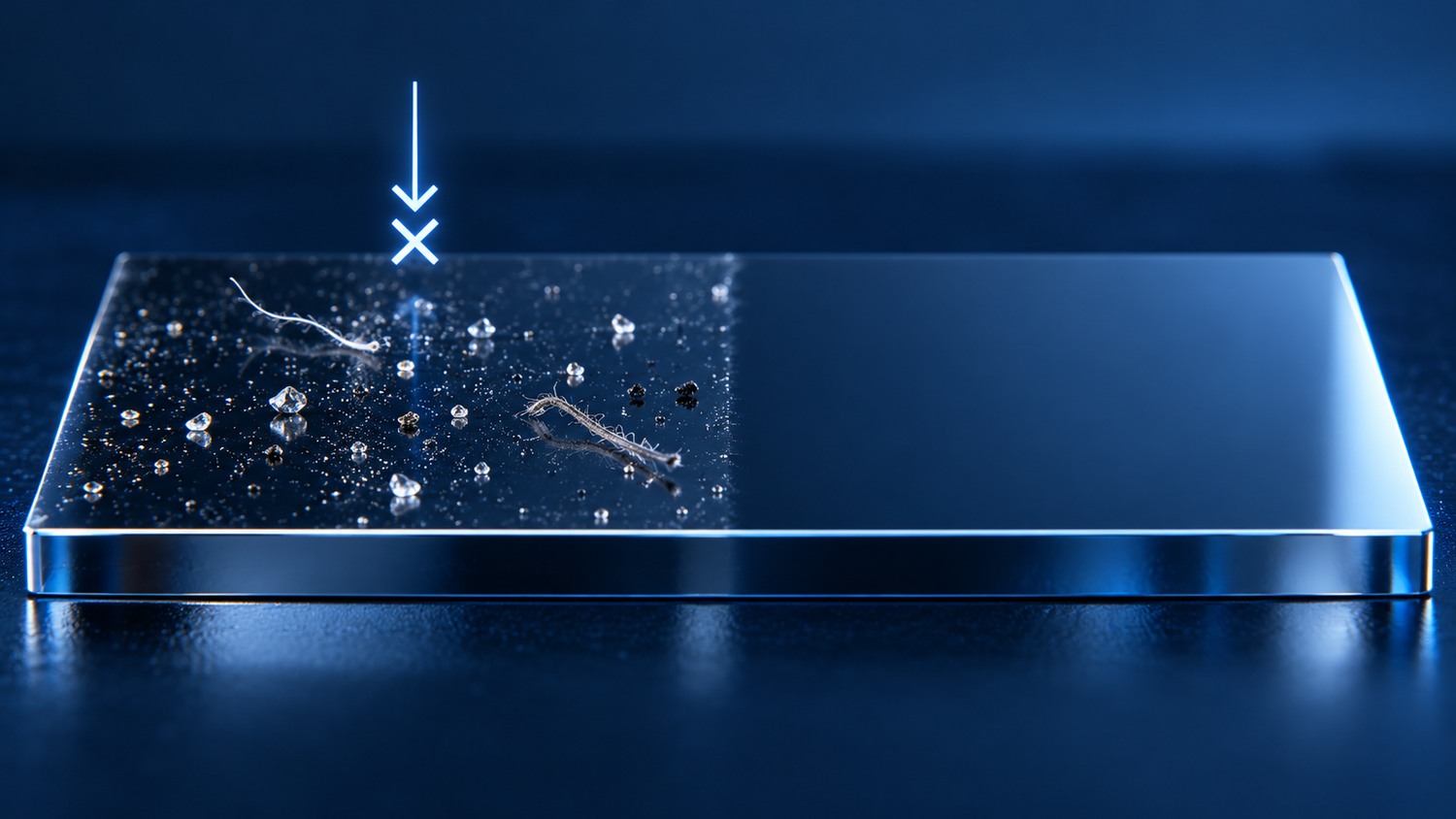
Original content by the OOTEE Optics editorial team, drawn from first-hand production line and inspection data. Please credit the source when republishing.
Given limits in expertise and test conditions, the theories, parameters and conclusions here carry no guarantee of absolute accuracy. For technical learning and exchange only - never the sole basis for design, acceptance or selection. Corrections welcome.

Cutting coated filter stock into usable parts is a manufacturing decision. Compare blade dicing, laser cutting and CNC contour grinding through five outcomes: edge-chip width, heat-affected zone, minimum kerf, shaped-hole capability and cost per accepted part. Dimensional tolerances and chamfer design are separate questions.
Here, diamond dicing means a rotating diamond blade cutting into glass, rather than scoring and snapping. CNC contour grinding uses diamond tools to generate profiles. “Laser cutting” needs a further distinction: material-removing ablation versus internal modification followed by separation. The latter may have no conventional open kerf and does not automatically produce a finished enclosed hole.
As Fig. 1 illustrates, blade abrasives can generate brittle chips on either face. Contour grinding can leave tool texture and local breakout. Laser ablation may introduce redeposited material, taper or thermal damage. Ultrashort pulses suppress heat diffusion, but repeated passes and coating absorption still require validation. Internal modification introduces a different concern: controlled crack propagation during separation.
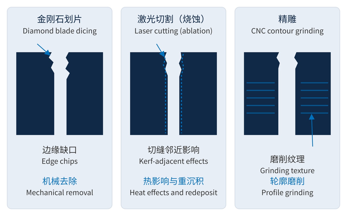
The three details share an observation scale, but their defect widths are conceptual, not a measured ranking. The laser panel represents ablation only. A technical note on thin-glass laser micromachining explains thermal-damage suppression; its results are not acceptance guarantees for coated filters.
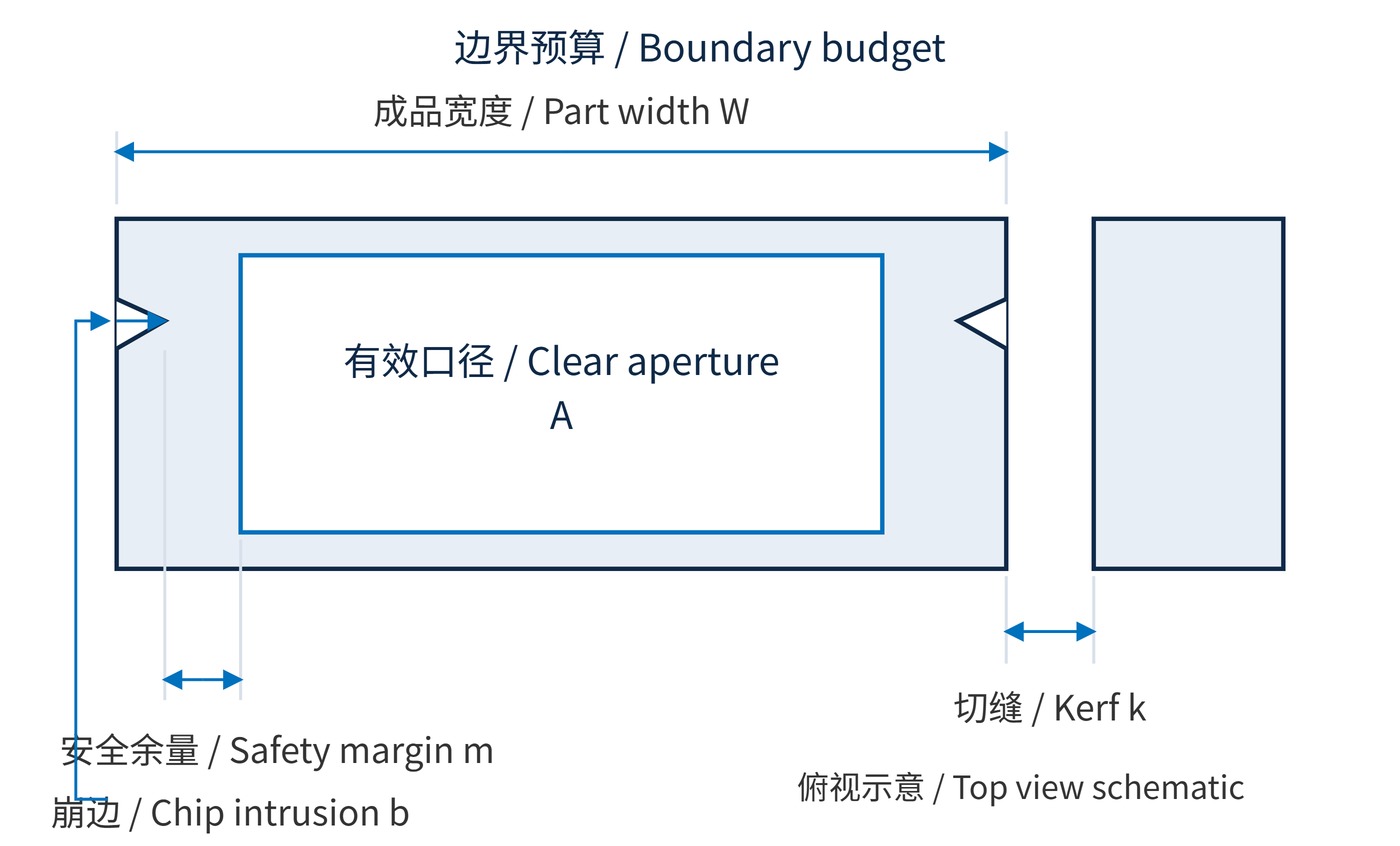
Measure maximum chip intrusion inward from the nominal finished edge, on both faces. Define the heat-affected zone (HAZ) by the inspection used: microscopy, stress birefringence or coating performance. Kerf is the width removed by the process. Minimum intact strip width is a different limit, governed by strength, support and handling.
Fig. 2 separates these boundaries. For a centered clear aperture of width $A$, part width $W$, maximum chip intrusion $b$ on each side and additional safety margin $m$:
$$A \leq W-2(b+m)$$
With $W=10\,\mathrm{mm}$, $b=0.05\,\mathrm{mm}$ and $m=0.10\,\mathrm{mm}$, the result is $A\leq9.70\,\mathrm{mm}$. This is a budgeting example, not a machine capability. Cracks or delamination extending farther inward require a larger damage allowance.
Fix the substrate, thickness, coated faces, geometry and lot size before requesting trials. An example brief could specify 0.5 mm coated glass, a 10 mm × 10 mm outline, maximum chips of 50 μm on either face and a 9.5 mm clear aperture. These are trial conditions, not universal recommendations. Record cutting tolerance and dimensional accuracy separately from damage limits.
| Process | Chips and thermal effects | Kerf and shaped holes | Suitable work and cost drivers |
|---|---|---|---|
| Diamond blade dicing | Check exit chips and coating lift; damage is primarily mechanical | Blade thickness and runout affect kerf; straight cuts suit arrays, enclosed shaped holes do not | Repeated rectangular parts; nesting, blade wear and yield drive cost |
| Laser cutting | Check ablation residue and heat effects, or separation cracks for internal modification | Narrow paths and complex profiles are possible; validate hole release and waste removal | Slender features and complex outlines; thickness, pass count and cleanup drive cycle time |
| CNC contour grinding | Check tool marks, chips and subsurface damage; support and coolant matter | Tool diameter limits slot width; internal corners need radii | Discs, steps and larger shaped holes; fixtures, tool changes and path length drive cost |
No single minimum kerf applies across thicknesses and laser routes. Request the measured kerf, narrowest intact strip, minimum internal radius and clean, two-sided inspection images. A smaller grinding tool has practical strength limits; tracing a laser contour does not prove that its enclosed waste can be removed safely.
For setup cost $C_{\mathrm{setup}}$, input quantity $N$, processing and cleanup cost $c_{\mathrm{run}}$ per input part, and accepted fraction $Y$, a simple comparison is:
$$c_{\mathrm{good}}=\frac{C_{\mathrm{setup}}+Nc_{\mathrm{run}}}{NY}$$
This model excludes mother-sheet cost. Add material, nesting loss and inspection on the same basis for every quote. A lower processing price can lose its advantage when yield falls.
Rectangular machine-vision filters often favor blade dicing when a mount masks the edge. Narrow probe elements, relief shapes and small holes justify laser trials, including checks for breakage during cleaning. Discs, locating notches and holes with rounded internal corners are natural candidates for contour grinding.
Use coupons with the actual coating stack for post-coating trials. Bare glass cannot establish coating compatibility. Cemented parts also require checks for adhesive response to coolant and laser absorption. Inspect both faces, hole walls, cleanliness and optical performance within the clear aperture.
Lasers are not universally chip-free, ultrashort pulses do not guarantee zero thermal damage, and CNC grinding is not always cheaper. Keep material, thickness, coating and acceptance conditions identical. Small visible chips do not rule out deeper cracks; confirm damage removal by sectioning or an appropriate strength test.
Conventional blade dicing is sufficient when parts have straight rectangular edges, need no enclosed shaped holes, tolerate the kerf loss, and keep verified chips and cracks outside the clear aperture. Stable yield after cleaning and assembly completes the case. Change routes when those conditions fail or a full cost comparison demonstrates a practical advantage.
 365nm Narrow Bandpass Filter | Ø50mm | T>90%
OT-HBP3659050
365nm Narrow Bandpass Filter; FWHM 10nm; transmission >90%; blocking OD5; size Ø50mm; AOI 0°.
 450nm Narrow Bandpass Filter | Ø50mm
OT-HBP4509050
450nm Narrow Bandpass Filter; FWHM 10nm; transmission >90%; blocking OD5; size Ø50mm; AOI 0°.
 525nm Narrow Bandpass Filter | Ø50mm
OT-HBP5259050
525nm Narrow Bandpass Filter; FWHM 10nm; transmission >90%; blocking OD5; size Ø50mm; AOI 0°.
Send us your drawing and spectral targets — an engineer replies with a feasibility check and quotation within one business day.