Original content by the OOTEE Optics editorial team, drawn from first-hand production line and inspection data. Please credit the source when republishing.
Given limits in expertise and test conditions, the theories, parameters and conclusions here carry no guarantee of absolute accuracy. For technical learning and exchange only - never the sole basis for design, acceptance or selection. Corrections welcome.

Cutting tolerance sets the permitted variation in a filter's diameter, length or width. Dimensional accuracy also depends on shape and location: roundness, straightness, squareness and the relationship to a datum may all matter. A tolerance is an allowed interval; a measured deviation describes one particular part. This article focuses on finished-part specifications and acceptance rather than machining methods.
A length of 20.00 ±0.05 mm permits values from 19.95 to 20.05 mm, a total tolerance of 0.10 mm. A unilateral requirement of 20.00 mm with deviations of +0/−0.10 mm prevents an oversized part, but increases the largest possible clearance. These specifications are therefore not interchangeable.
As Fig. 1 illustrates, a profile zone limits where an actual edge may lie. The illustration does not imply that a length tolerance automatically controls the entire perimeter. Size, form and location need explicit drawing requirements.
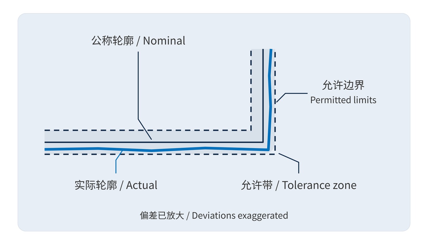
A circular filter may need both diameter and roundness limits. A rectangle may need length, width, straightness and squareness. Notches and locating flats require datums and position requirements. Define which physical edge is measured: the apparent opening left by a chamfer is not the same as the outside dimension. Specify the clear aperture separately.
For a bore diameter $D$ and glass diameter $d$, the limiting diametral clearances are, before allowing for form errors or temperature differences:
$$C_{\min}=D_{\min}-d_{\max},\qquad C_{\max}=D_{\max}-d_{\min}$$
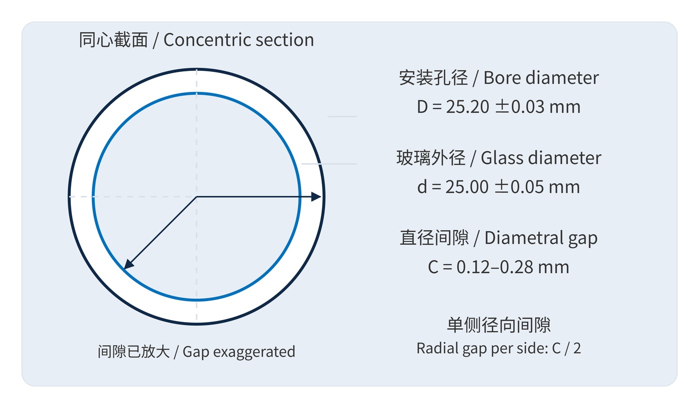
A 25.20 ±0.03 mm bore and a 25.00 ±0.05 mm filter yield a diametral clearance of 0.12–0.28 mm. With ideal concentric positioning, the radial gap on each side is half that value: 0.06–0.14 mm. Fig. 2 shows why both components must be evaluated together. These are worked examples, not stated manufacturing capabilities. Adhesive, seals and eccentricity change the available space.
Mechanical compliance does not establish spectral compliance. A filter specified at center wavelength (CWL) 780 nm, full width at half maximum (FWHM) 20 nm and optical density (OD) 6 still needs separate spectral acceptance conditions, including the wavelength range and angle of incidence (AOI).
Start with the mounting space, locating features and clear aperture. Allocate the available variation between the glass and its holder. A worst-case fit analysis must also address form, thermal expansion and assembly offset. A root-sum-square calculation alone cannot guarantee assembly for every combination of limiting dimensions.
| Drawing item | Define explicitly | Inspection concern |
|---|---|---|
| Diameter or length and width | Nominal size and upper/lower deviations in mm | Directions and sampling locations |
| Form and location | Roundness, squareness or profile; relevant datums | Local dimensions can miss protrusions |
| Edges and clear aperture | Chamfer boundary, notches and usable optical area | Separate mechanical and optical boundaries |
| Inspection agreement | Temperature, equipment and decision rule | Disposition of borderline results |
Vision measurement is useful for planar contours, but transparent edges, reflective coatings and illumination affect edge detection. Contact measurement requires controlled force and a defined contact location away from chamfers. Agree on the measurement section, directions and reported values. The dimensional reference temperature is normally 20 °C; the NIST dimensional metrology guidance explains the temperature convention.
If both parties adopt a conservative guard-band rule, a result $x$ with expanded uncertainty $U$ is accepted only when its uncertainty interval stays within the lower and upper limits $L$ and $H$:
$$x-U\geq L,\qquad x+U\leq H$$
For limits of 19.95–20.05 mm, a result of 20.047 mm with $U=0.008\,\mathrm{mm}$ fails that acceptance condition. It requires the agreed follow-up, such as remeasurement; it does not prove that the part is out of tolerance. This guard band is an agreed decision rule, not a default requirement for every order.
For machine vision filters mounted ahead of a lens, clearance must accommodate assembly while limiting decentering and aperture obstruction. A tighter fit can introduce clamping stress. Locating features should establish position, with suitable allowance for retention and temperature changes.
Filters sharing a wheel need consistent locating edges and inspection datums. Check interference at the largest part size, looseness at the smallest size, and beam clearance at the greatest permitted offset. Length and width alone rarely describe the fit of a shaped part.
A usable specification states the permitted size, the reference geometry, where measurements are taken and how borderline results are judged. Consistent definitions make a dimensional report useful for assembly decisions.
 365nm Narrow Bandpass Filter | Ø50mm | T>90%
OT-HBP3659050
365nm Narrow Bandpass Filter; FWHM 10nm; transmission >90%; blocking OD5; size Ø50mm; AOI 0°.
 450nm Narrow Bandpass Filter | Ø50mm
OT-HBP4509050
450nm Narrow Bandpass Filter; FWHM 10nm; transmission >90%; blocking OD5; size Ø50mm; AOI 0°.
 525nm Narrow Bandpass Filter | Ø50mm
OT-HBP5259050
525nm Narrow Bandpass Filter; FWHM 10nm; transmission >90%; blocking OD5; size Ø50mm; AOI 0°.
Send us your drawing and spectral targets — an engineer replies with a feasibility check and quotation within one business day.