Original content by the OOTEE Optics editorial team, drawn from first-hand production line and inspection data. Please credit the source when republishing.
Given limits in expertise and test conditions, the theories, parameters and conclusions here carry no guarantee of absolute accuracy. For technical learning and exchange only - never the sole basis for design, acceptance or selection. Corrections welcome.

Center wavelength (CWL) places a band on the wavelength axis. Full width at half maximum (FWHM) measures its width at half the peak transmission. “Half maximum” describes the measurement height; the reported width is the full distance between the two crossings.
For a single transmission band, this article defines CWL as the arithmetic midpoint of its short- and long-wavelength half-maximum crossings. FWHM is their separation. Confirm this convention when comparing specifications: a peak wavelength or another declared center metric may be used instead.
$$T(\lambda_1)=T(\lambda_2)=\frac{T_{\mathrm{peak}}}{2}$$
$$\lambda_{\mathrm{CWL}}=\frac{\lambda_1+\lambda_2}{2},\qquad \Delta\lambda_{\mathrm{FWHM}}=\lambda_2-\lambda_1$$
Fig. 1 uses a 90% peak, so the measurement line is 45% transmission. Crossings at 770 nm and 790 nm give CWL 780 nm and FWHM 20 nm. They do not establish a 90% transmission window across those wavelengths.
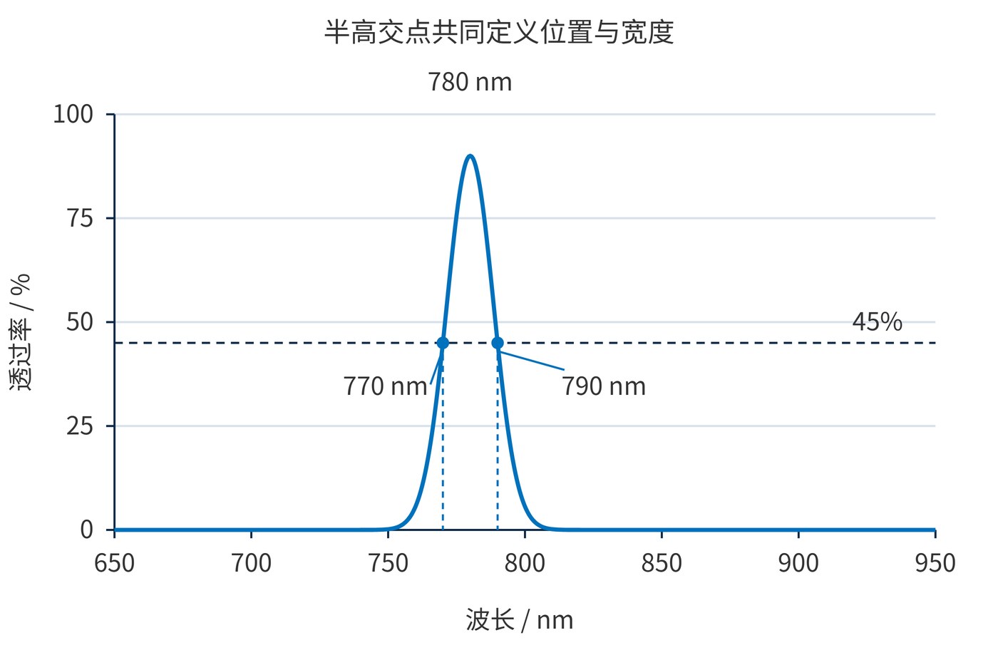
In an interference bandpass filter, optical layer thicknesses and coupling establish the transmission band. CWL and FWHM describe the resulting spectrum; they do not uniquely identify the coating design. A rounded band and a flat-topped band can share both values while transmitting different amounts of signal.
For a symmetric single peak, its wavelength coincides with the midpoint of the half-maximum crossings. An asymmetric band need not behave that way. Multiple peaks or substantial ripple require an agreed band selection and crossing rule before one FWHM value is meaningful.
Optical density (OD) specifies rejection, while angle of incidence (AOI) establishes part of the operating geometry. A 780 nm center and 20 nm FWHM imply no particular rejection level. OD6 means transmission no greater than 0.0001%, and needs an explicit wavelength interval.
Signal throughput depends on overlap with the entire spectrum. With incident spectral power density $S(\lambda)$ and dimensionless transmission $T(\lambda)$:
$$P_{\mathrm{out}}=\int S(\lambda)T(\lambda)\,\mathrm{d}\lambda$$
The same calculation applies to background. Narrowing a band helps when it removes background while retaining useful signal. If the desired emission is broad, a narrower filter may discard substantial signal as well.
Start with the wavelength interval the instrument must retain. Then allocate center and bandwidth tolerances, allowing for source drift, source variation and the installed beam geometry. Nominal alignment alone cannot establish coverage.
Consider CWL 780 ± 2 nm and FWHM 20 ± 2 nm. The minimum width is 18 nm. With the midpoint convention above, the common half-maximum coverage across all allowed combinations is only 773–787 nm, as Fig. 2 shows. This is an independent worst-case tolerance calculation, not a prediction of production statistics.
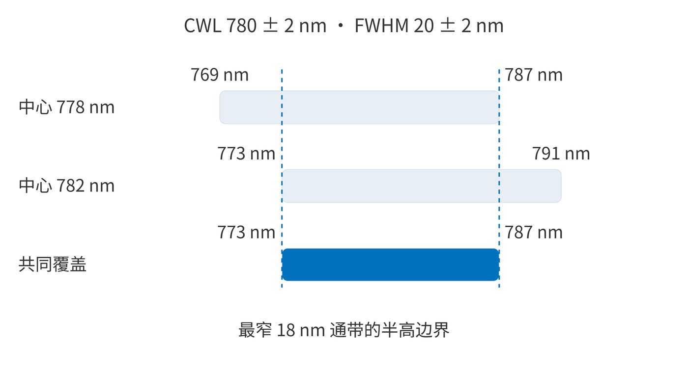
A signal spanning 774–786 nm fits inside that interval, but this alone does not guarantee high transmission. If every wavelength must transmit at least 85%, specify that requirement separately and verify it under the intended angle, temperature and polarization.
| Requirement | Illustrative specification |
|---|---|
| Position and width | CWL 780 ± 2 nm; FWHM 20 ± 2 nm |
| Useful signal interval | Minimum transmission ≥85% over 774–786 nm |
| Rejection | OD ≥6 over 400–740 nm and 820–1000 nm |
| Reference conditions | AOI 0°, collimated beam, 23 ± 2 °C, unpolarized light |
These are examples of specification language; joint feasibility requires a design assessment. A converging beam also needs a cone-angle specification. Reports should state spectral resolution, sampling interval and wavelength accuracy so instrumental broadening is not mistaken for filter bandwidth.
For incoming inspection, calculate both crossing wavelengths from the same measured trace and the same declared peak reference. Record the interpolation method when a crossing falls between samples. If the instrument cannot resolve the edges adequately, a finer sampling grid alone will not recover the missing spectral detail. Agreement on this procedure helps distinguish a genuine center or width deviation from a difference in data processing.
Laser-line detection can use a narrow band to reduce background, provided source drift, filter center tolerance and angular variation fit within the available margin. As bandwidth approaches the total drift budget, alignment and temperature control become more demanding.
Fluorescence detection needs a balance between integrated emission throughput and excitation leakage. Centering on the emission peak does not necessarily maximize useful signal. In multichannel instruments, evaluate overlap and gaps between neighboring bands as well as their center spacing.
A verifiable specification combines the crossing convention, center and width tolerances, minimum signal-band transmission, and blocking intervals under common measurement conditions.
Definition reference: Optical filter terminology and half-power boundaries. Figures and tolerance calculations are independent illustrative models, not measured product data.
 365nm Narrow Bandpass Filter | Ø50mm | T>90%
OT-HBP3659050
365nm Narrow Bandpass Filter; FWHM 10nm; transmission >90%; blocking OD5; size Ø50mm; AOI 0°.
 450nm Narrow Bandpass Filter | Ø50mm
OT-HBP4509050
450nm Narrow Bandpass Filter; FWHM 10nm; transmission >90%; blocking OD5; size Ø50mm; AOI 0°.
 525nm Narrow Bandpass Filter | Ø50mm
OT-HBP5259050
525nm Narrow Bandpass Filter; FWHM 10nm; transmission >90%; blocking OD5; size Ø50mm; AOI 0°.
Send us your drawing and spectral targets — an engineer replies with a feasibility check and quotation within one business day.



