Original content by the OOTEE Optics editorial team, drawn from first-hand production line and inspection data. Please credit the source when republishing.
Given limits in expertise and test conditions, the theories, parameters and conclusions here carry no guarantee of absolute accuracy. For technical learning and exchange only - never the sole basis for design, acceptance or selection. Corrections welcome.
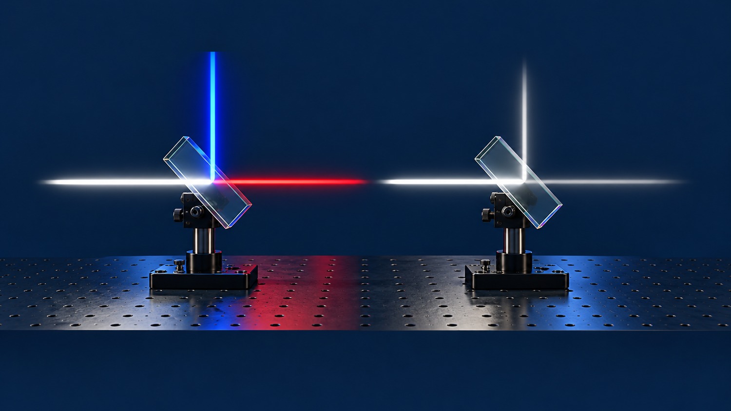
A dichroic mirror routes wavelengths to different output ports through selective reflection and transmission. A coating might reflect blue light while transmitting red light. It redistributes wavelengths already present in the input; it does not convert one color into another. Dichroic mirrors are therefore a wavelength-selective class of beamsplitter.
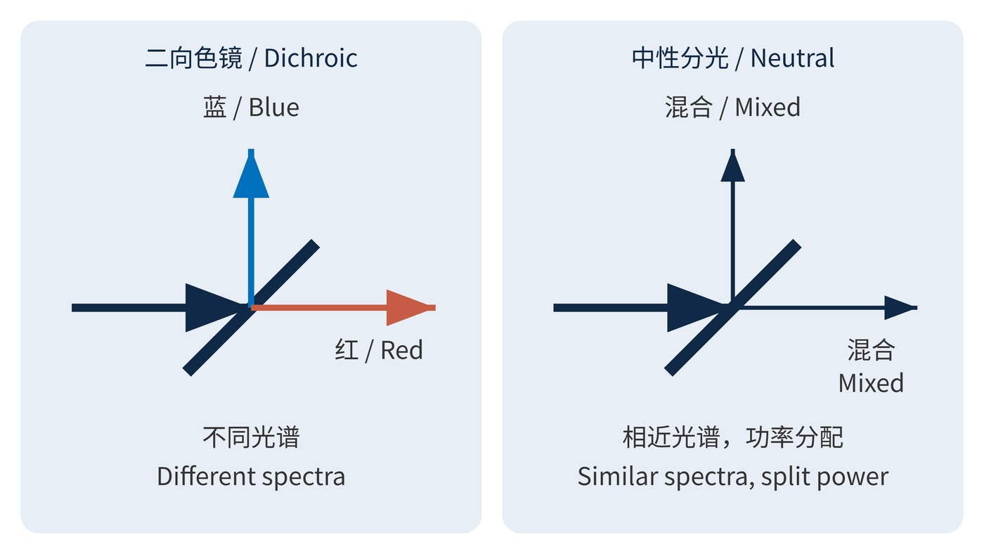
A nominal 50:50 beamsplitter has a different objective: approximately equal reflected and transmitted powers over a specified wavelength range, polarization and angle. For an ideal neutral splitter, both outputs retain the input spectral shape. A dichroic produces different output spectra, as Fig. 1 illustrates. Neither behavior should be assumed outside the specified operating range. This distinction matters whenever the two outputs feed detectors that must measure different signals rather than duplicate one signal.
In a dielectric coating, reflections from multiple interfaces interfere. Layer thicknesses and refractive indices determine which wavelengths are preferentially reflected or transmitted. The round-trip propagation phase within one layer is:
$$\delta = \frac{4\pi n d\cos\theta_t}{\lambda}$$
Here, $n$ is refractive index, $d$ is layer thickness and $\theta_t$ is the angle inside that layer. This phase alone does not predict the complete spectrum: interface phase changes and all layers must be included in a multilayer calculation.
For a given wavelength and polarization, normalize all channels to the same incident power. With absorption $A$ and scattering $S$ treated separately, conservation requires:
$$R(\lambda)+T(\lambda)+A(\lambda)+S(\lambda)=1$$
The approximation $R+T=1$ is useful only when the other losses are negligible. Low transmission is not, by itself, evidence that the missing power reaches the reflected port.
Angle of incidence (AOI) is measured from the surface normal. At 45°, the reflected propagation direction turns by 90°. The s and p polarization responses can differ, including their transition wavelengths. Reflection bands, transmission bands and the transition region are the primary specifications. Center wavelength (CWL) and full width at half maximum (FWHM) describe bandpass features; they do not replace a two-port definition.
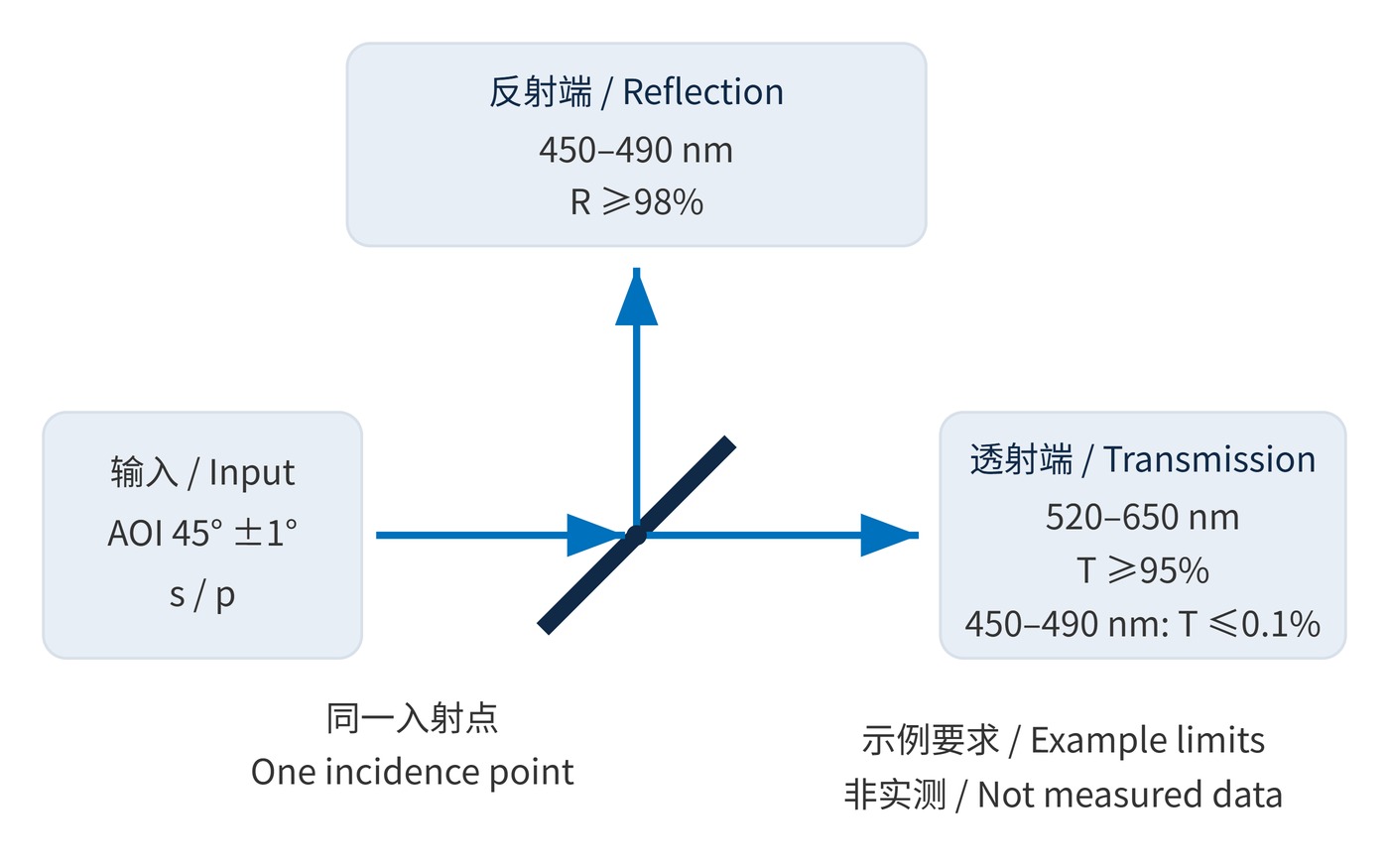
Start with the source spectrum, desired signal and detector response. Then state where each band must go. The following is a hypothetical acceptance specification, not a product rating. The transition interval is deliberately excluded from both useful bands.
| Item | Example requirement | Acceptance check |
|---|---|---|
| Geometry | AOI 45° ±1°, in air | Cover the actual angular range |
| Reflected port | 450–490 nm, R ≥98% | Meet limits for s and p separately |
| Transmitted port | 520–650 nm, T ≥95% | Specify a band minimum |
| Transition | 490–520 nm | Keep critical spectral lines clear |
| Port crosstalk | T ≤0.1% at 450–490 nm | State measurement floor and bandwidth |
Transmission leakage can be expressed as optical density (OD): $\mathrm{OD}=-\log_{10}T$, with $T$ as a fractional power ratio. Thus 0.1% corresponds to OD3. This limits light entering the transmitted port; it does not specify reflected efficiency.
Output powers also depend on how the source distributes power across wavelength:
$$P_R=\int P_{\lambda}(\lambda)R(\lambda)\,\mathrm{d}\lambda,\qquad P_T=\int P_{\lambda}(\lambda)T(\lambda)\,\mathrm{d}\lambda$$
$P_{\lambda}$ is incident spectral power density. Efficient separation of two bands does not imply equal total output powers. As Fig. 2 shows, measure both ports under the intended AOI, polarization and aperture conditions. Imaging systems also need reflected wavefront, transmitted aberration and rear-surface ghost checks.
In epi-fluorescence microscopy, a dichroic reflects excitation toward the objective while transmitting longer-wavelength fluorescence toward detection. An emission filter provides additional excitation rejection. The dichroic routes the beams; its specification alone cannot determine the complete system background.
Multichannel imaging can send visible and near-infrared bands to separate sensors. Laser systems can separate a fundamental wavelength from its harmonic. Compatible ports can also combine different wavelengths into one path. Reverse operation still requires checking coating orientation, polarization and beam overlap rather than assuming that flipping the optic preserves every system property.
A complete acceptance test establishes spectral routing, wavefront performance and leakage at both working ports. A single cutoff wavelength cannot do that. The Florida State University microscopy primer’s chapter on prisms and beamsplitters covers the supporting definitions and beam geometry.
 365nm Narrow Bandpass Filter | Ø50mm | T>90%
OT-HBP3659050
365nm Narrow Bandpass Filter; FWHM 10nm; transmission >90%; blocking OD5; size Ø50mm; AOI 0°.
 450nm Narrow Bandpass Filter | Ø50mm
OT-HBP4509050
450nm Narrow Bandpass Filter; FWHM 10nm; transmission >90%; blocking OD5; size Ø50mm; AOI 0°.
 525nm Narrow Bandpass Filter | Ø50mm
OT-HBP5259050
525nm Narrow Bandpass Filter; FWHM 10nm; transmission >90%; blocking OD5; size Ø50mm; AOI 0°.
Send us your drawing and spectral targets — an engineer replies with a feasibility check and quotation within one business day.