Original content by the OOTEE Optics editorial team, drawn from first-hand production line and inspection data. Please credit the source when republishing.
Given limits in expertise and test conditions, the theories, parameters and conclusions here carry no guarantee of absolute accuracy. For technical learning and exchange only - never the sole basis for design, acceptance or selection. Corrections welcome.

An optical filter is environmentally reliable when it retains its required function under an agreed exposure and measurement procedure. Qualification needs a baseline, controlled exposure and a defined recovery assessment. A clean-looking surface after testing is only one part of the evidence.
The test article matters. A bare optic does not qualify its adhesive, retaining ring or seal. Conversely, a sealed module passing salt fog does not establish that its internal filter tolerates direct salt exposure. Identify the assembly state, exposed surfaces and clear aperture before testing.
A useful report therefore states exactly what was qualified and under which conditions. Its conclusion should remain tied to that configuration rather than silently extending to other installations.
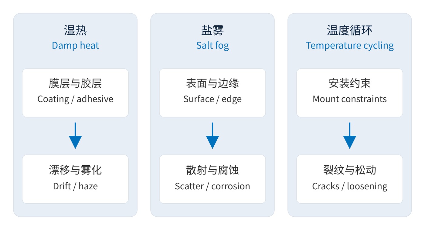
Damp heat can affect moisture uptake, interfaces and adhesives. Salt fog can create scattering deposits and attack metal mounts or exposed interfaces. Temperature cycling repeatedly loads materials with different expansion coefficients. Fig. 1 connects each stress to an entry route and a functional consequence.
A first estimate of differential free thermal strain is:
$$\Delta\varepsilon=(\alpha_1-\alpha_2)\Delta T$$
The expansion coefficients $\alpha_1$ and $\alpha_2$ have units of $\mathrm{K}^{-1}$. This is not a stress calculation: stiffness, adhesive compliance, constraints and temperature gradients also matter. Slow cycling and rapid thermal shock are not equivalent simply because their endpoints match.
Record center wavelength (CWL), full width at half maximum (FWHM), peak transmission and optical density (OD), with a fixed angle of incidence (AOI), polarization and measurement position. Define residual wavelength change at the same reference temperature $T_0$:
$$\Delta\lambda_{\mathrm{res}}=\lambda_{\mathrm{after}}(T_0)-\lambda_{\mathrm{before}}(T_0)$$
A shift during exposure may reverse after recovery. Residual change assesses persistence; it does not establish performance while the instrument is operating in the environment.
Start with the installation and its exposure history: temperature, humidity, condensation and salt access. Environmental test standards define methods; the application determines severity and acceptance. IEC 60068-2-78 addresses constant-temperature, high-humidity exposure without condensation. A condensing environment needs an appropriate additional method.
| Exposure | Conditions to agree | Assessment priorities |
|---|---|---|
| Damp heat | Temperature, relative humidity, duration, condensation state | Residual spectrum, haze, adhesive changes |
| Salt fog | Solution, pH, collection rate, duration, cleaning procedure | Scatter, corrosion, edges and seals |
| Temperature cycling | Endpoints, specimen dwell, ramp or transfer time, cycle count | Cracks, delamination, loosening and spectrum |
For a CWL 780 nm, FWHM 20 nm filter, an illustrative agreement could limit recovered CWL change to ±1 nm and peak transmission loss to 2 percentage points, while retaining OD6 over 400–700 nm. These are example acceptance limits, not product claims. OD6 means transmission no greater than 0.0001%; the instrument must have adequate stray-light control and dynamic range.
Likewise, 85 °C at 85% relative humidity for 168 h, or 100 cycles between −40 °C and +85 °C, are possible project conditions rather than universal requirements. Define dwell using specimen temperature, not merely the chamber setpoint.
Specify how each limit will be measured. A blocking requirement needs a wavelength interval, not just an OD value at one wavelength. A transmission change also needs an unambiguous convention: a fall from 95% to 93% is 2 percentage points. Keep the illuminated area and measurement geometry consistent so that a different spot or angle does not masquerade as environmental damage.
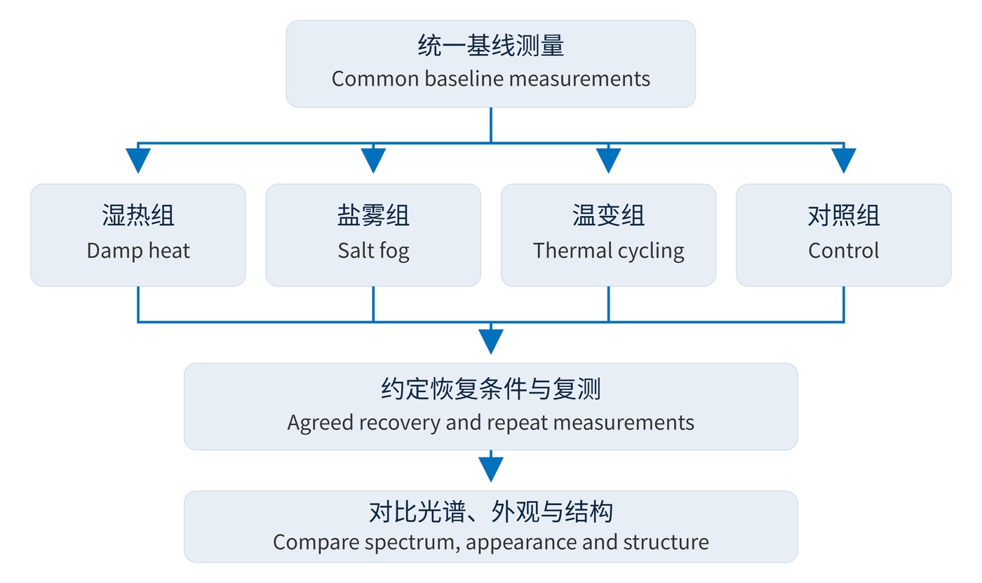
Fig. 2 shows separate exposure groups with a retained control. Use a dedicated sequential group when investigating coupled damage, such as cycling followed by damp heat. Agree the inspection, cleaning and recovery sequence for salt-exposed samples before starting.
Record the condition before cleaning as well as the recovered result. Otherwise, removal of surface deposits can hide the reason for a temporary optical failure. Keep sample identities and lot information attached to every measurement, and distinguish a separate-stress screening result from evidence obtained after a specified sequence of stresses. These answer different qualification questions.
For coastal cameras, qualify the window, mount and seal pathways that actually meet the environment. Direct exposure of a bare internal optic may misrepresent service. ISO 9227 salt spray methods assess corrosion resistance of metallic materials; optical assemblies also need transmission, scatter and cleaning criteria.
Outdoor ranging systems using narrow bandpass filters need both in-environment spectral overlap with the source and stable recovered performance. Test production-representative mounting or bonding. For indoor instruments shipped through cold storage, include packaging, condensation during unpacking and the recovery procedure.
Acceptance should combine operating function, recovered spectral change and structural integrity, with measurement uncertainty included at the decision boundary. Traceable conditions and comparable before-and-after data make the conclusion reproducible.
 365nm Narrow Bandpass Filter | Ø50mm | T>90%
OT-HBP3659050
365nm Narrow Bandpass Filter; FWHM 10nm; transmission >90%; blocking OD5; size Ø50mm; AOI 0°.
 450nm Narrow Bandpass Filter | Ø50mm
OT-HBP4509050
450nm Narrow Bandpass Filter; FWHM 10nm; transmission >90%; blocking OD5; size Ø50mm; AOI 0°.
 525nm Narrow Bandpass Filter | Ø50mm
OT-HBP5259050
525nm Narrow Bandpass Filter; FWHM 10nm; transmission >90%; blocking OD5; size Ø50mm; AOI 0°.
Send us your drawing and spectral targets — an engineer replies with a feasibility check and quotation within one business day.



