Original content by the OOTEE Optics editorial team, drawn from first-hand production line and inspection data. Please credit the source when republishing.
Given limits in expertise and test conditions, the theories, parameters and conclusions here carry no guarantee of absolute accuracy. For technical learning and exchange only - never the sole basis for design, acceptance or selection. Corrections welcome.
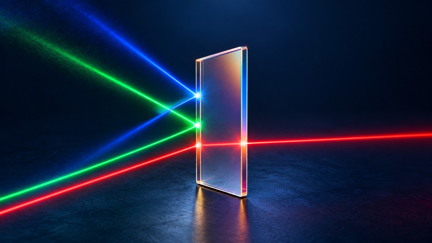
An optical filter assigns a different transmission to each wavelength. It passes a useful spectral region while attenuating unwanted light. It does not normally convert rejected wavelengths into useful ones or turn a broadband source into a laser. Selection, signal throughput and background rejection must work together at the detector.
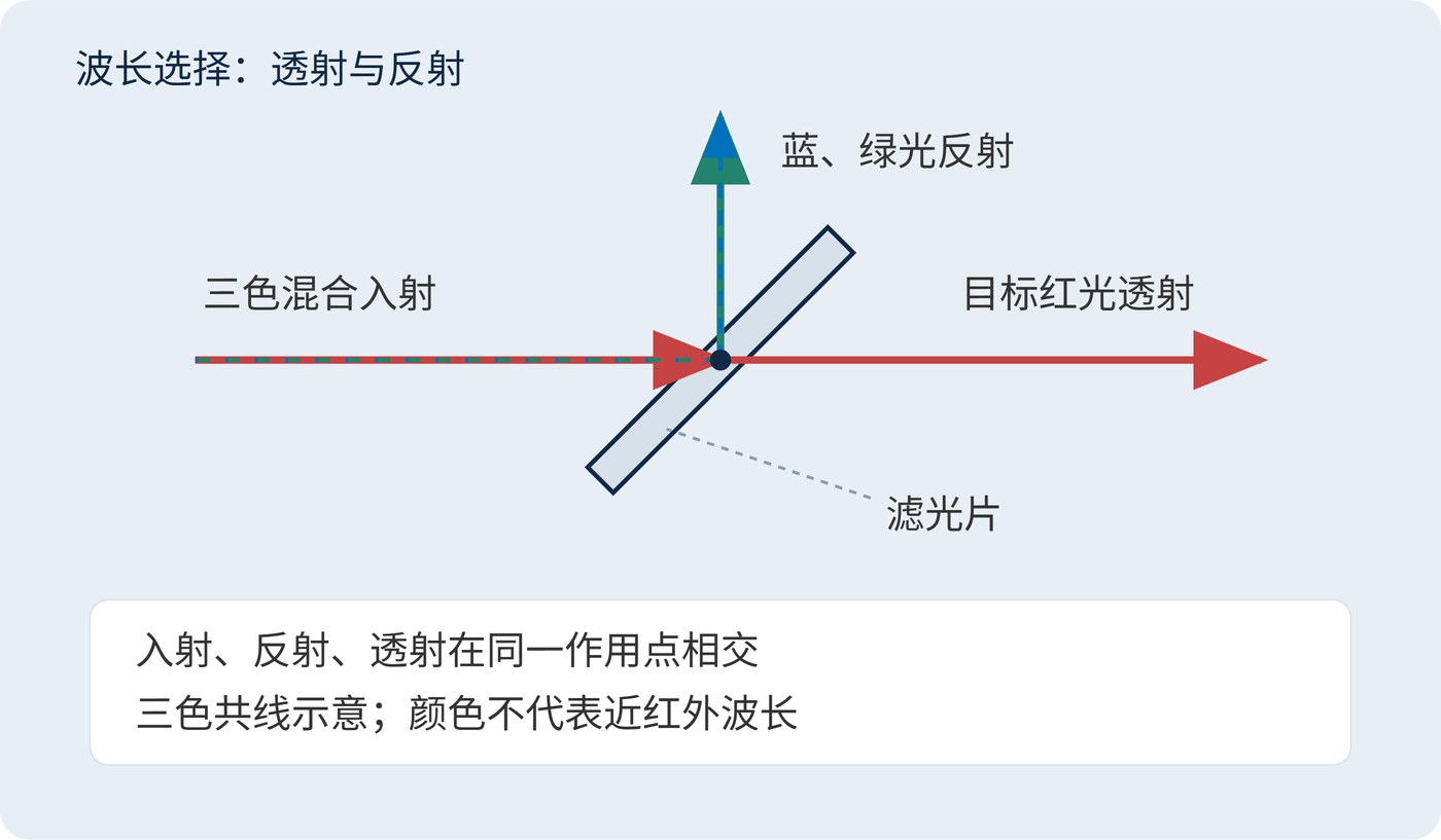
Fig. 1 illustrates this with three visible colors: one is transmitted and the others are reflected. The colors explain the routing rather than representing a 780 nm near-infrared application. Real passbands have finite width and finite loss.
Dielectric coatings create wavelength selectivity through interference between reflected waves. Absorbing materials instead remove selected spectral regions through absorption. For a passive element with negligible scattering and no wavelength conversion, the power fractions at a given wavelength satisfy:
$$T(\lambda)+R(\lambda)+A(\lambda)=1$$
Here $T$, $R$ and $A$ are transmittance, reflectance and absorptance. Rejected light still needs somewhere to go: reflected light may need a beam dump, while absorbed power can heat the element. Missing power in a limited-aperture transmission measurement cannot automatically be assigned to absorption.
Center wavelength (CWL) locates the passband. Full width at half maximum (FWHM) spans the two half-peak crossings; it is not a half-width. Optical density (OD) expresses attenuation at a specified wavelength, using fractional transmittance rather than a percentage:
$$\mathrm{OD}(\lambda)=-\log_{10}T(\lambda)$$
OD6 means 0.0001% transmission, but only over the wavelengths actually specified. Angle of incidence (AOI), cone angle, polarization and temperature define the operating conditions. A normal-incidence trace alone does not establish performance in a converging beam.
Background reaching a detector depends on more than filter transmission. Let $P_{\mathrm{b}}(\lambda)$ be incident background spectral power density in W/nm and $r(\lambda)$ detector responsivity in A/W. The resulting background photocurrent is:
$$i_{\mathrm{b}}=\int_{\lambda_{\min}}^{\lambda_{\max}}P_{\mathrm{b}}(\lambda)T(\lambda)r(\lambda)\,\mathrm{d}\lambda$$
Integrate across the region where incident light and detector sensitivity overlap. The same approach applies to the target spectrum. A small remote transmission leak can matter greatly where illumination is intense and detector responsivity is high.
For a narrow signal near 780 nm, a CWL of 780 nm and FWHM of 20 nm could be a starting point. The following discussion example is only part of a specification. Transmission across 770–790 nm still needs a separate agreement.
| Item | Example requirement | Purpose |
|---|---|---|
| Signal window | 775–785 nm; minimum transmission 90% | Retain signal and drift margin |
| Strong interference | OD6 at 650 nm | Limit a known bright source |
| Other blocking | At least OD4 over 400–750 nm and 810–1100 nm | Cover the assumed detector range |
| Conditions | AOI 0°; beam half-cone angle at most 2°; 20 °C | Define when the requirements apply |
Suppose 650 nm interference is 100000 times stronger than the target and detector responsivity is equal at both wavelengths. OD6 leaves background equal to 0.1 times the unfiltered target. With 90% target transmission, the remaining background is about 11% of the transmitted signal. Deep blocking must therefore be judged against the actual input ratio.
This calculation concerns a single interfering line, not an entire broadband background. For broadband illumination, sum the transmitted contributions across the detector range using the integral above. Also distinguish guaranteed blocking from the measurement instrument's noise floor: an apparently flat trace at very low transmission may report a measurement limit rather than the filter's true leakage. Leave transition regions explicit instead of silently treating the gap between passband and specified blocking as fully rejected light.
In industrial inspection, a filter matched to narrow-spectrum illumination can reduce out-of-band ambient light and stabilize image contrast. Ambient light within the same band still passes. In fluorescence detection, excitation leakage may greatly exceed emission, making both spectral isolation and mechanical light control necessary.
A useful system check records the target with illumination enabled, then measures background under the same exposure and detector settings. Repeat with external light excluded to identify environmental contributions. If background remains after the intended optical path is blocked, investigate assembly gaps or internal reflections before demanding a deeper blocking specification. These checks connect the filter requirement to the instrument's actual limitation.
Fig. 2 separates in-band background, out-of-band leakage and bypass light. Spectral filtering addresses the first two according to their wavelengths; baffles, apertures and sealed housings address bypass paths. Modulated illumination and synchronous detection may help separate same-band background. A filter alone cannot identify whether a photon came from the sample or the room.
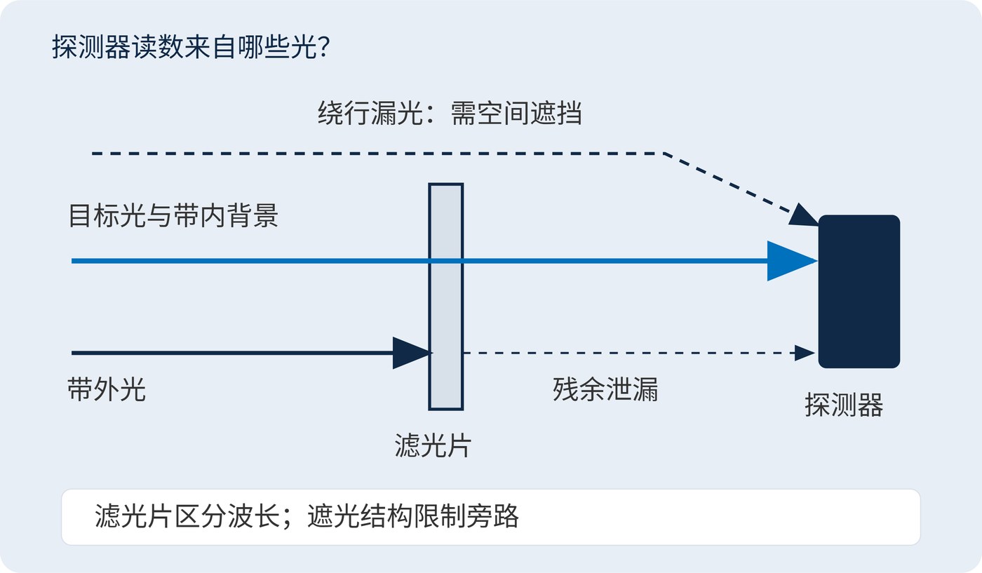
Acceptance should specify spectral intervals and operating conditions, then verify signal and background in the instrument. The useful result is sufficient target throughput with spectrally separable interference reduced to the measurement budget.
 365nm Narrow Bandpass Filter | Ø50mm | T>90%
OT-HBP3659050
365nm Narrow Bandpass Filter; FWHM 10nm; transmission >90%; blocking OD5; size Ø50mm; AOI 0°.
 450nm Narrow Bandpass Filter | Ø50mm
OT-HBP4509050
450nm Narrow Bandpass Filter; FWHM 10nm; transmission >90%; blocking OD5; size Ø50mm; AOI 0°.
 525nm Narrow Bandpass Filter | Ø50mm
OT-HBP5259050
525nm Narrow Bandpass Filter; FWHM 10nm; transmission >90%; blocking OD5; size Ø50mm; AOI 0°.
Send us your drawing and spectral targets — an engineer replies with a feasibility check and quotation within one business day.