Original content by the OOTEE Optics editorial team, drawn from first-hand production line and inspection data. Please credit the source when republishing.
Given limits in expertise and test conditions, the theories, parameters and conclusions here carry no guarantee of absolute accuracy. For technical learning and exchange only - never the sole basis for design, acceptance or selection. Corrections welcome.
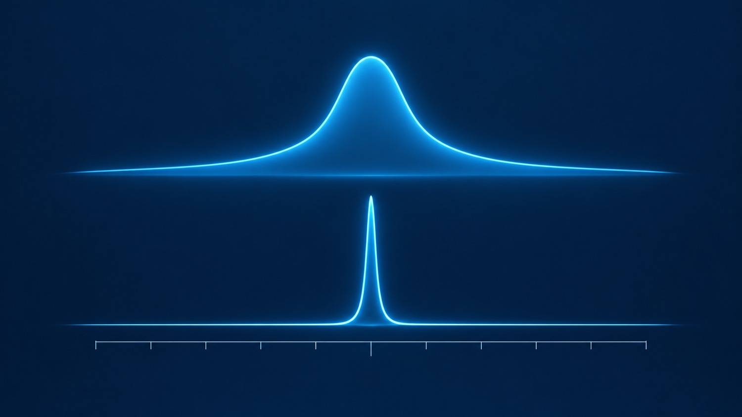
A monochromatic filter selects a limited spectral band from broadband or mixed light. The term describes a purpose rather than a universally defined bandwidth class. Its output still has finite bandwidth, and filtering an ordinary lamp does not give it laser coherence.
A laser line filter is usually a bandpass filter designed around a specified laser wavelength. It passes that line while suppressing unwanted emission or background. These categories overlap: the useful distinction is whether transmission, blocking and operating conditions are specified around a particular laser line.
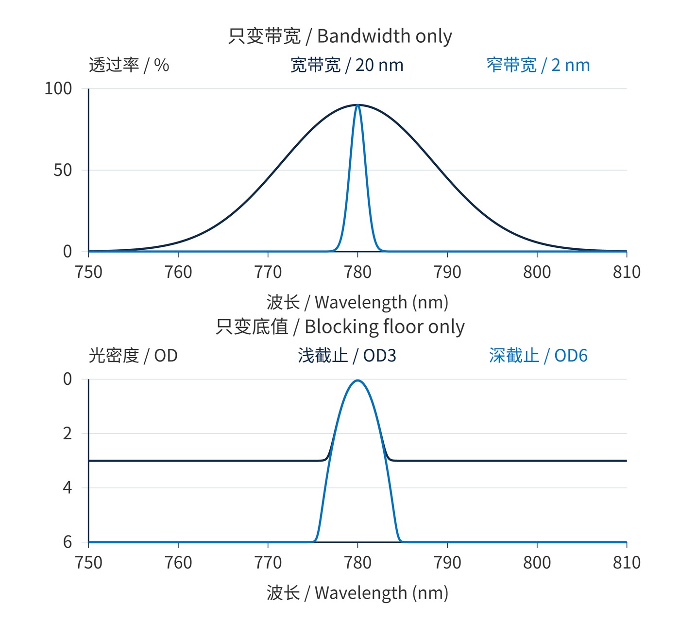
Fig. 1 separates two properties often bundled together in cover illustrations: bandwidth and rejection depth. A laser line designation alone guarantees neither a narrower passband nor deeper blocking.
Both types can use multilayer dielectric interference coatings. Center wavelength (CWL) locates the passband. Full width at half maximum (FWHM) measures the distance between the half-peak crossings; it does not define a guaranteed high-transmission interval.
$$T(\lambda_1)=T(\lambda_2)=\frac{T_{\mathrm{peak}}}{2},\qquad \mathrm{FWHM}=\lambda_2-\lambda_1$$
Optical density (OD) describes attenuation using power transmission $T$ expressed as a fraction. OD6 means $T=10^{-6}$, or 0.0001%. A blocking claim needs wavelength limits: it cannot be extended to every wavelength outside the passband.
$$\mathrm{OD}(\lambda)=-\log_{10}T(\lambda)$$
The curves in Fig. 1 come from a Gaussian-passband plus constant-floor model, with CWL 780 nm and peak transmission 90%. The upper panel changes only FWHM, from 20 nm to 2 nm, at an OD3 floor. The lower panel holds FWHM at 2 nm and changes only the floor, from OD3 to OD6. Sampling is 0.1 nm. These analytical examples are not measured products and do not model coating sidebands.
Angle of incidence (AOI) changes the interference condition; tilting generally shifts the passband toward shorter wavelengths. A small shift can substantially reduce transmission through a narrow peak. Evaluate $T(\lambda_{\mathrm{L}})$ under the actual angle, cone and temperature, rather than relying on $T_{\mathrm{peak}}$.
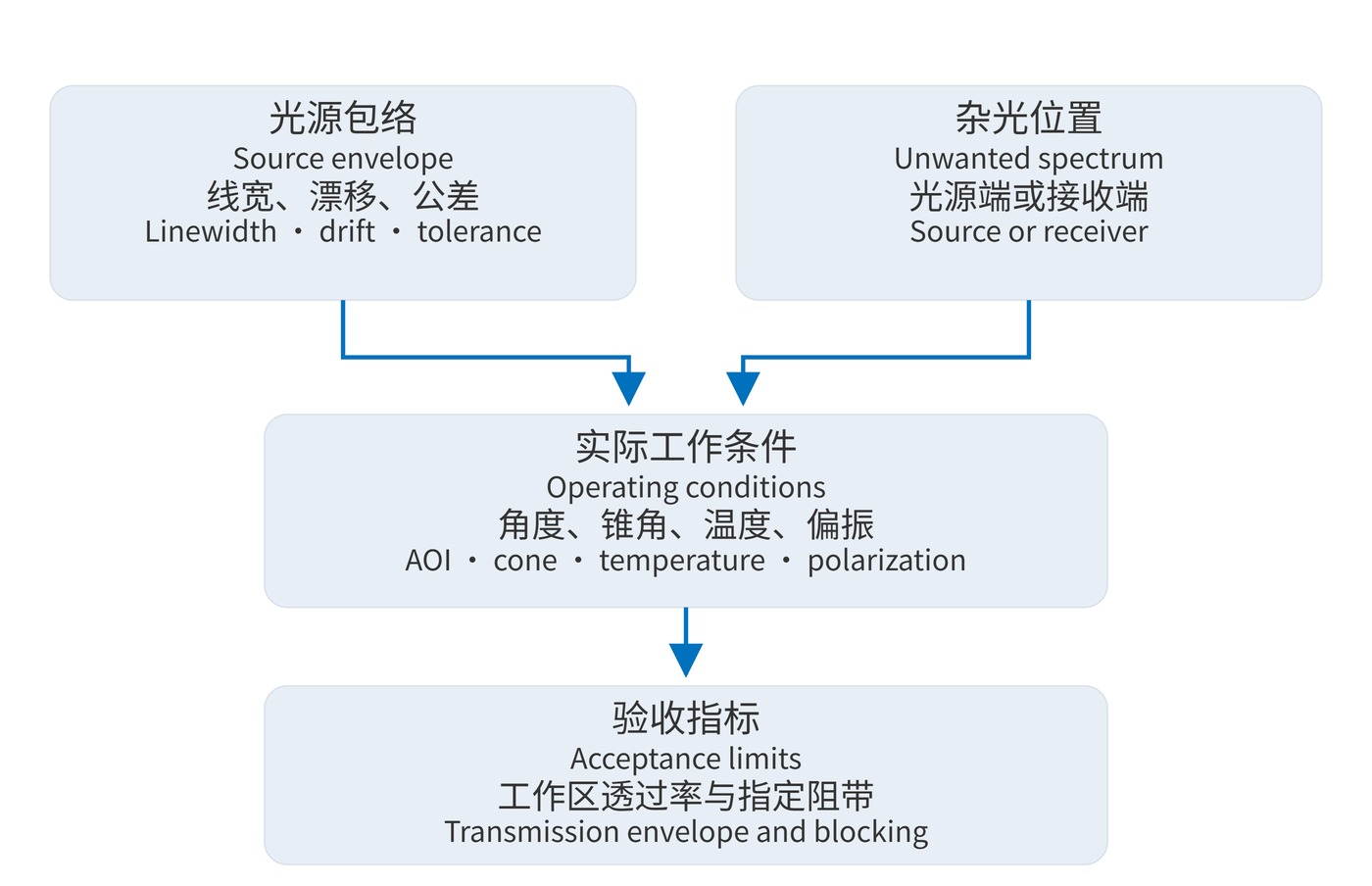
Start with the spectrum that must reach the next stage. Combine source linewidth, wavelength tolerance, temperature drift and angular variation into an operating envelope. Specify minimum transmission across that envelope. Fig. 2 shows why source contamination and receiver background require separate checks.
| Item | Band selection example | Laser line example |
|---|---|---|
| Position and width | CWL 780 nm; FWHM 20 nm | CWL 780 nm; FWHM 2 nm |
| Transmission acceptance | ≥70% over 775–785 nm | ≥85% over 779.8–780.2 nm |
| Blocking | OD3 over 400–750 nm and 810–1000 nm | OD6 over 400–770 nm and 790–1000 nm |
| Reference conditions | AOI 0°; 20 °C; collimated beam | AOI 0°; 20 °C; collimated beam |
These are independent requirement examples, not product promises or specifications for Fig. 1. A wider source envelope requires a new bandwidth budget. Also define polarization, clear aperture, allowable cone angle and continuous power density or pulse fluence. The name does not establish a laser damage threshold.
Request spectral coverage across the detector's sensitive range and sufficient scan resolution to resolve the passband. A flat OD6 trace may reflect the instrument floor. Acceptance evidence should identify stray-light control, noise floor and measurement uncertainty.
For example, checking transmission only at nominal 780 nm misses a source that moves toward a passband edge during warm-up. Ask for the worst transmission across the full source envelope, including wavelength tolerance. Similarly, a blocking measurement at a single remote wavelength says little about leakage close to the transition region. Keep the transmission interval, transition allowance and blocking intervals separate in the drawing, then verify each against the intended optical geometry.
In an excitation path, a laser line filter can suppress unwanted source emission before it reaches the sample. It transmits the excitation line. A detection path intended to reject scattered excitation instead needs a suitable line-rejection solution; a transmitting filter cannot directly substitute for it.
For active imaging, a receiver bandpass can reduce ambient background around the illumination wavelength. However, rays at the field edge may see a shifted passband. Broader illumination spectra or larger acceptance angles can justify a wider filter. Compare integrated useful signal and background before tightening the bandwidth.
Compare useful signal, integrated background and measurable acceptance limits under the same operating conditions. Once those are defined, the choice of terminology becomes secondary to an engineering specification.
 365nm Narrow Bandpass Filter | Ø50mm | T>90%
OT-HBP3659050
365nm Narrow Bandpass Filter; FWHM 10nm; transmission >90%; blocking OD5; size Ø50mm; AOI 0°.
 450nm Narrow Bandpass Filter | Ø50mm
OT-HBP4509050
450nm Narrow Bandpass Filter; FWHM 10nm; transmission >90%; blocking OD5; size Ø50mm; AOI 0°.
 525nm Narrow Bandpass Filter | Ø50mm
OT-HBP5259050
525nm Narrow Bandpass Filter; FWHM 10nm; transmission >90%; blocking OD5; size Ø50mm; AOI 0°.
Send us your drawing and spectral targets — an engineer replies with a feasibility check and quotation within one business day.