Original content by the OOTEE Optics editorial team, drawn from first-hand production line and inspection data. Please credit the source when republishing.
Given limits in expertise and test conditions, the theories, parameters and conclusions here carry no guarantee of absolute accuracy. For technical learning and exchange only - never the sole basis for design, acceptance or selection. Corrections welcome.
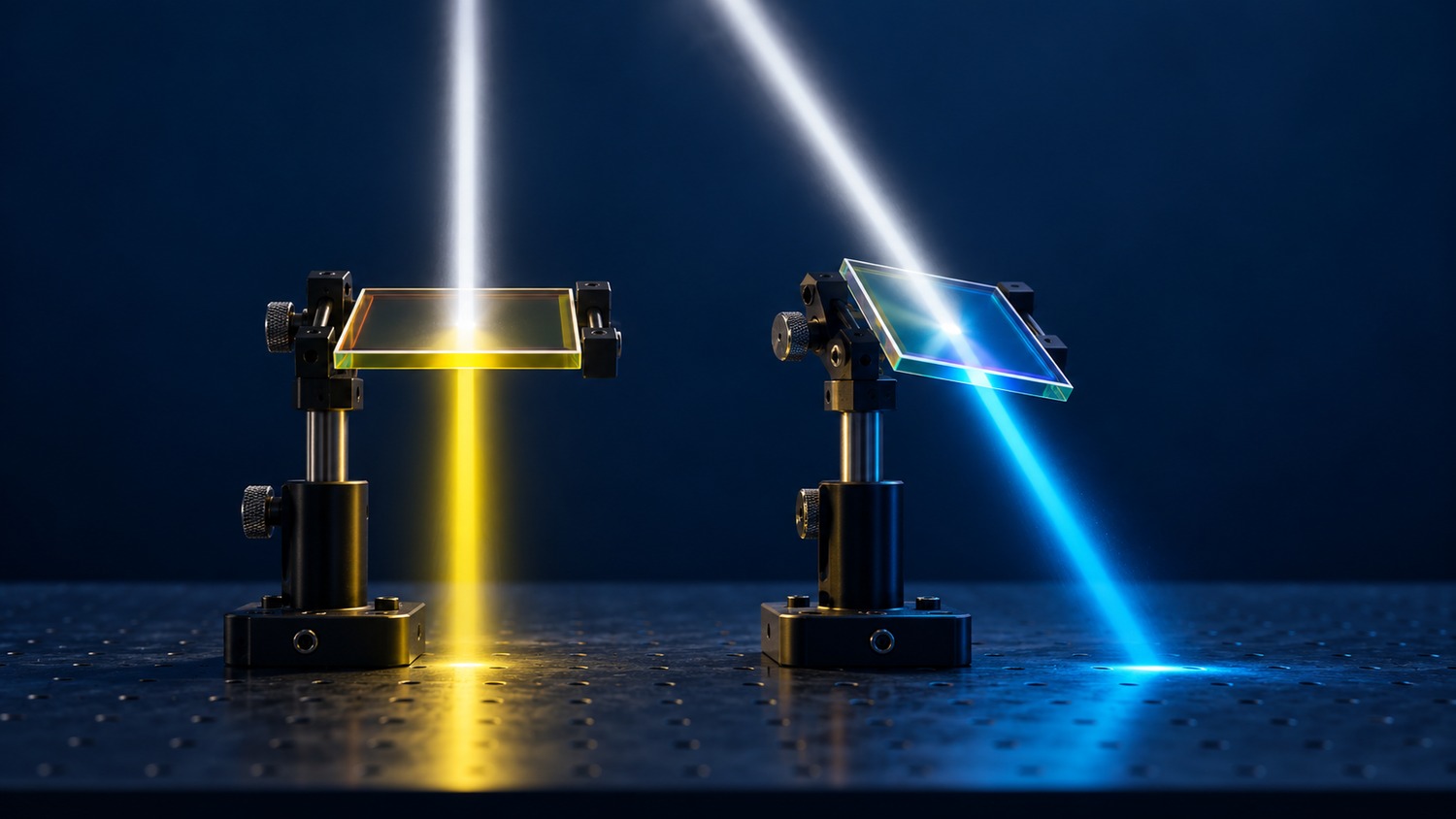
Angle of incidence (AOI) is measured from the surface normal. For an interference filter, its importance extends beyond a shift in center wavelength (CWL): an imaging lens delivers a distribution of angles, so the detector receives an averaged spectral response.
This article treats angle as a system budget. Full width at half maximum (FWHM) and optical density (OD) need defined illumination conditions. Absorptive filter glass follows different physics; the interference model below should not be applied to it directly.
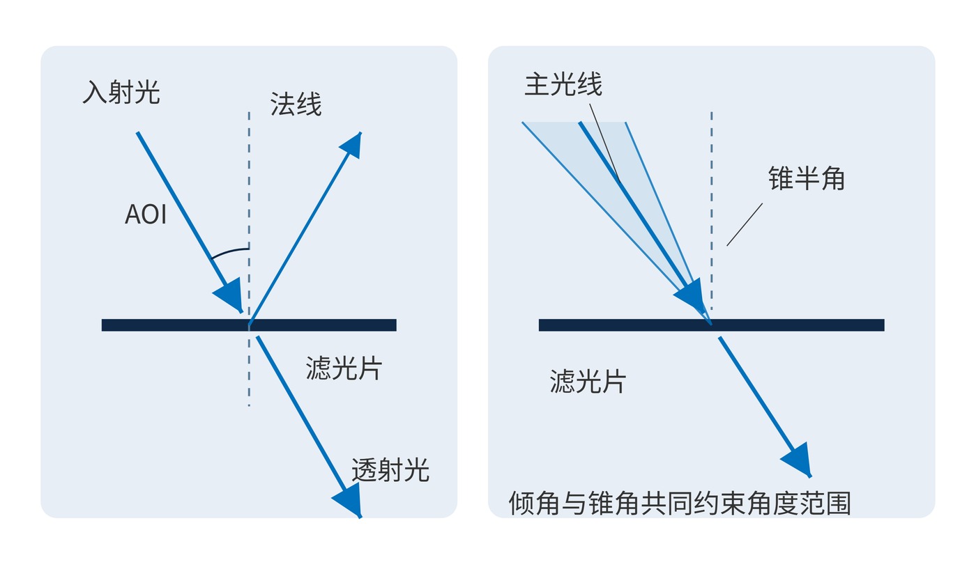
Fig. 1 distinguishes beam direction from angular spread. Mount tilt, field angle and lens aperture all contribute. A nominal AOI of 0° does not fully describe a converging beam. Two assemblies using the same filter can consequently deliver different signal levels at the detector.
Tilting changes propagation angles and phase within the coating. A spectral feature usually moves toward shorter wavelengths. For incidence from air, an effective-index approximation is:
$$\lambda(\theta)\approx\lambda_0\sqrt{1-\frac{\sin^2\theta}{n_{\mathrm{eff}}^2}}$$
The external angle is $\theta$. The coating's effective index $n_{\mathrm{eff}}$ is design, wavelength and polarization dependent; it is not the substrate index. Use this estimate for screening, with coating calculations or measurements for large angles.
With $\lambda_0=780\,\mathrm{nm}$ and $n_{\mathrm{eff}}=1.8$, the estimated centers at 10°, 20° and 30° are 776.4 nm, 765.8 nm and 749.3 nm. The 30° shift exceeds a 20 nm FWHM. Even 10° can matter when the signal lies near an edge. These numbers alone predict neither peak loss nor blocking degradation.
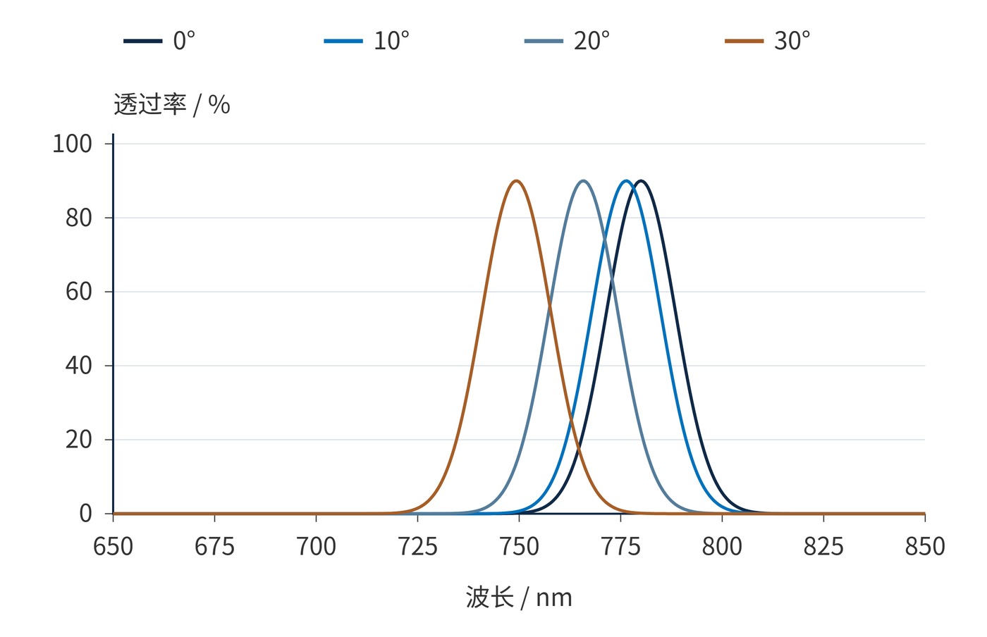
Fig. 2 uses a Gaussian band sampled every 0.5 nm: normal-incidence CWL 780 nm, FWHM 20 nm, peak 90%, effective index 1.8. Only AOI changes, translating the profile. This is an illustrative model, without polarization splitting, bandwidth changes or realistic blocking leakage.
A detector combines rays rather than measuring only the chief ray. With normalized angular power weights $w(\theta,\phi)$, the effective transmission is:
$$T_{\mathrm{eff}}(\lambda)=\int_{\Omega}w(\theta,\phi)T(\lambda,\theta,\phi)\,\mathrm{d}\Omega,\qquad\int_{\Omega}w\,\mathrm{d}\Omega=1$$
Angular averaging can round a passband and soften its edges. At oblique incidence, S and P responses can separate as well. Apply the actual polarization weights when evaluating unpolarized or partially polarized illumination.
Extract ray angles across the full field and pupil, then include assembly tolerance. For preliminary screening, chief ray tilt $\beta$ and cone half angle $\alpha$ give a maximum AOI of $\beta+\alpha$. Use ray tracing for the final envelope. In air, $\alpha\approx\arctan[1/(2N)]$ is a useful small-angle estimate for working f-number $N$.
| Specification item | Example requirement or verification |
|---|---|
| Geometry and polarization | Chief ray 0° to 10°, cone half angle 5°; declare polarization |
| Signal transmission | Angularly averaged transmission ≥85% throughout 775–785 nm |
| Background rejection | Example: OD≥6 over 400–700 nm at agreed angles and polarizations |
| Comparable measurements | Report spot size, cone angle, spectral resolution and extreme-angle spectra |
These are example requirements, not product claims. At 15°, the model predicts an 8.1 nm shift. That is enough to revisit wavelength tolerance, thermal allowance and bandwidth. Moving the filter into a more collimated section or designing for the intended angle may help; widening the band requires a fresh background budget.
In fluorescence imaging, marginal rays in a fast converging beam can lose overlap with the emission window. A collimated section reduces cone angle, but field-dependent chief ray tilt still needs checking. Compare central and edge pixels before attributing shading entirely to illumination.
For narrow-line laser receivers, transmission at the fixed laser wavelength matters more than the displaced peak. If tilt is introduced to suppress return reflections, include it in the spectral budget and test under the receiving cone.
A useful acceptance sequence is to measure collimated spectra at the angular extremes first, then assess the weighted response of the actual illumination. Record which side faces the incident beam and keep temperature and illuminated area consistent. If a field point fails, distinguish a systematic spectral mismatch from coating nonuniformity before changing the specification. A favorable spectrum at the center of the field cannot establish performance at its edge.
Accept the angular envelope against minimum effective transmission in the signal window, maximum leakage in the background window and response variation across the field. These criteria connect a component measurement to the signal and background that the instrument actually detects.
 365nm Narrow Bandpass Filter | Ø50mm | T>90%
OT-HBP3659050
365nm Narrow Bandpass Filter; FWHM 10nm; transmission >90%; blocking OD5; size Ø50mm; AOI 0°.
 450nm Narrow Bandpass Filter | Ø50mm
OT-HBP4509050
450nm Narrow Bandpass Filter; FWHM 10nm; transmission >90%; blocking OD5; size Ø50mm; AOI 0°.
 525nm Narrow Bandpass Filter | Ø50mm
OT-HBP5259050
525nm Narrow Bandpass Filter; FWHM 10nm; transmission >90%; blocking OD5; size Ø50mm; AOI 0°.
Send us your drawing and spectral targets — an engineer replies with a feasibility check and quotation within one business day.



