Original content by the OOTEE Optics editorial team, drawn from first-hand production line and inspection data. Please credit the source when republishing.
Given limits in expertise and test conditions, the theories, parameters and conclusions here carry no guarantee of absolute accuracy. For technical learning and exchange only - never the sole basis for design, acceptance or selection. Corrections welcome.

An infrared cut-off filter, or IR-cut filter, transmits visible light while suppressing near-infrared radiation in the imaging path. It commonly forms part of the optical stack ahead of the sensor. Silicon charge-coupled devices (CCDs) and complementary metal-oxide-semiconductor (CMOS) sensors remain sensitive beyond visible red, potentially approaching 1100 nm depending on their construction.
A color filter array does not provide equivalent rejection. Near-infrared contamination enters the color channels in different proportions. Two fabrics that look equally black can therefore photograph differently because their infrared reflectance differs. White balance scales channel signals; it cannot uniquely separate visible and infrared contributions. Camera documentation confirms that removing the filter admits infrared alongside visible light.
The signal in color channel $c$ depends on illumination $E$, object reflectance $\rho$, lens transmission $L$, filter transmission $T$, and channel response $Q_c$:
$$S_c\propto\int E(\lambda)\rho(\lambda)L(\lambda)T(\lambda)Q_c(\lambda)\,\mathrm{d}\lambda$$
Here $Q_c$ includes the color array. As Fig. 1 shows, declining sensor sensitivity does not make infrared leakage irrelevant when the illumination contains substantial infrared energy. The normalized response is neither quantum efficiency nor a measurement of a particular sensor.
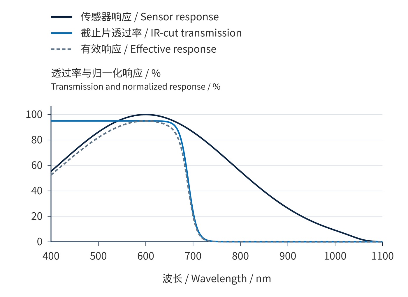
Fig. 1 uses 1 nm sampling: $q(\lambda)=\exp[-((\lambda-600\,\mathrm{nm})/(260\,\mathrm{nm}))^2]/\{1+\exp[(\lambda-1050\,\mathrm{nm})/(15\,\mathrm{nm})]\}$ and $T(\lambda)=0.001+0.949/\{1+\exp[(\lambda-690\,\mathrm{nm})/(9\,\mathrm{nm})]\}$. Normalizing $q$ to its maximum over the plotted interval gives $Q$; the effective response is $QT$. Conditions are normal incidence without temperature drift. These explanatory curves are not a coating design or product specification.
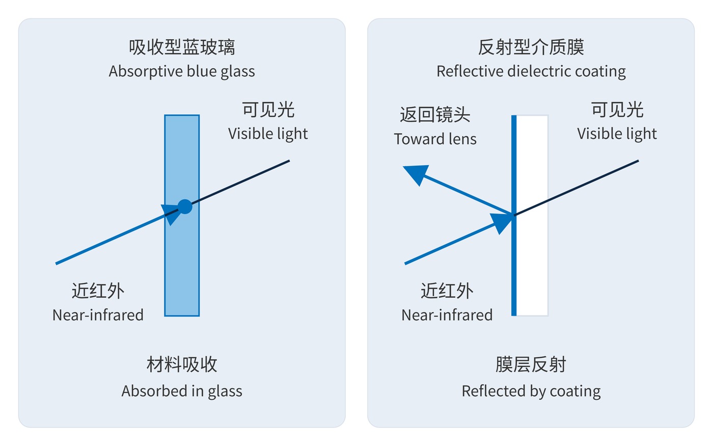
Absorptive blue glass dissipates infrared inside the substrate. A reflective design uses dielectric layers to return it toward the lens. Blue glass avoids the pronounced interference-edge shift, but an oblique ray travels farther through it and can experience different attenuation. Reflective filters offer steep edges, with greater dependence on angle of incidence (AOI). A fast lens produces a cone of angles even when its chief ray is near normal.
The role of absorption in reducing returning energy is discussed in an absorptive-material technical description; performance in an assembled camera still requires measurement. Optical density (OD) must apply across a stated wavelength interval:
$$\mathrm{OD}(\lambda)=-\log_{10}T(\lambda),\qquad T=10^{-\mathrm{OD}}$$
OD3 means 0.1% transmission. Center wavelength (CWL) and full width at half maximum (FWHM) describe bandpass filters. For IR-cut selection, specify the edge criterion—such as absolute 50% transmission—plus the visible passband and infrared rejection interval.
An illustrative starting specification is average transmission ≥90% over 420–650 nm, OD≥3 throughout 700–1000 nm, and an absolute 50% edge at 680±5 nm at normal incidence. This is not a universal camera standard: retaining deep red competes with infrared rejection. When evaluating shortpass filters, request curves at 0°, 15°, and 25°, then compare them with the actual chief-ray angles and cone limits.
Fig. 2 contrasts the energy paths. Blue glass reduces infrared available for return paths, yet its surfaces still reflect and need suitable antireflection treatment. Strong infrared reflection alone does not guarantee a recorded ghost: the returned light must encounter another reflecting interface, pass through the filter, and reach the sensor. Sensor reflectivity, spacing, tilt, and bright point sources matter.
Separate mechanical vignetting from spectral shading. A small clear aperture clips rays; longer paths in blue glass can increase off-axis loss; an angle-shifted coating edge can attenuate deep red more strongly near the frame boundary. None is inevitable. Test flat fields and bright point sources across focal lengths, apertures, and focus distances.
A useful acceptance record keeps these observations separate. Compare center and corner RAW channel ratios before applying lens-shading correction, and retain the exposure settings. For ghosts, move the point source both inside and just outside the frame. A uniform brightness correction may hide attenuation while leaving a change in spectral balance unresolved.
Portraiture, reproduction, and textile photography require consistent visible color. Include materials with different infrared reflectance rather than relying solely on a gray card. Repeat under daylight and an infrared-rich source: calibration under one illuminant can conceal leakage that becomes apparent under another.
Infrared conversion changes the intended spectral band. Simply removing the IR-cut filter yields a broader response, limited by the lens and remaining windows; it does not isolate infrared. A visible-blocking filter is generally needed. Removing a plane-parallel plate also changes the optical path. Match replacement thickness and refractive index, then check autofocus, infinity focus, and aberrations. Infrared focusing guidance notes that calibration can vary with lens and focal length.
Conversion therefore needs a new reference condition: the chosen infrared band, lens, and working aperture. Successful focus at one setting does not establish performance across a zoom range. Color obtained after conversion should be treated as a different rendering objective rather than an extension of the original visible-light calibration.
Judge the assembled camera using RAW-channel flat-field consistency, material color errors, and point-source ghosts. Record aperture, field position, and illumination spectrum with each result.
 365nm Narrow Bandpass Filter | Ø50mm | T>90%
OT-HBP3659050
365nm Narrow Bandpass Filter; FWHM 10nm; transmission >90%; blocking OD5; size Ø50mm; AOI 0°.
 450nm Narrow Bandpass Filter | Ø50mm
OT-HBP4509050
450nm Narrow Bandpass Filter; FWHM 10nm; transmission >90%; blocking OD5; size Ø50mm; AOI 0°.
 525nm Narrow Bandpass Filter | Ø50mm
OT-HBP5259050
525nm Narrow Bandpass Filter; FWHM 10nm; transmission >90%; blocking OD5; size Ø50mm; AOI 0°.
Send us your drawing and spectral targets — an engineer replies with a feasibility check and quotation within one business day.