Original content by the OOTEE Optics editorial team, drawn from first-hand production line and inspection data. Please credit the source when republishing.
Given limits in expertise and test conditions, the theories, parameters and conclusions here carry no guarantee of absolute accuracy. For technical learning and exchange only - never the sole basis for design, acceptance or selection. Corrections welcome.

A solar selective absorber belongs on the receiver: it absorbs sunlight while limiting thermal emission at operating temperature. A filter sits in an optical path and distributes wavelengths through transmission and reflection. These functions are distinct, as described in the national laboratory review of selective absorber surfaces.
“High temperature” is incomplete without an atmosphere, exposure duration, irradiance and temperature gradient. The substrate, coating and mount must all qualify. Fig. 1 illustrates a useful arrangement: place a robust window at the hot boundary and keep wavelength selection in a cooler compartment.
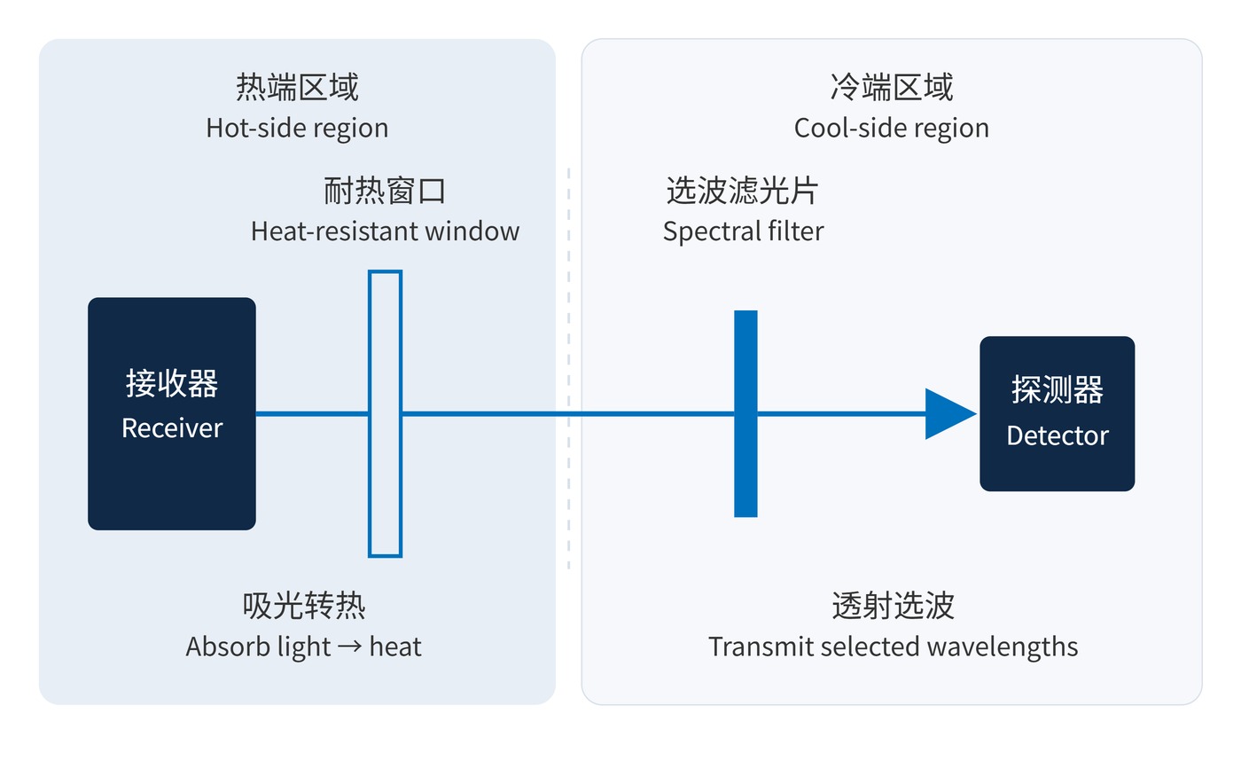
At a specified wavelength, temperature and incidence angle, energy conservation gives:
$$T(\lambda)+R(\lambda)+A(\lambda)=1$$
Rejected radiation becomes a thermal load when it is absorbed. Optical density (OD) alone says nothing about that load: OD4 means 0.01% transmission. Specify center wavelength (CWL), full width at half maximum (FWHM), angle of incidence (AOI) and beam cone angle. Angular blue shift can otherwise be mistaken for temperature drift.
Over a limited interval with a stable coating, a local approximation is:
$$\lambda_{\mathrm{c}}(\vartheta)=\lambda_{\mathrm{c}}(\vartheta_0)+k_T(\vartheta-\vartheta_0)$$
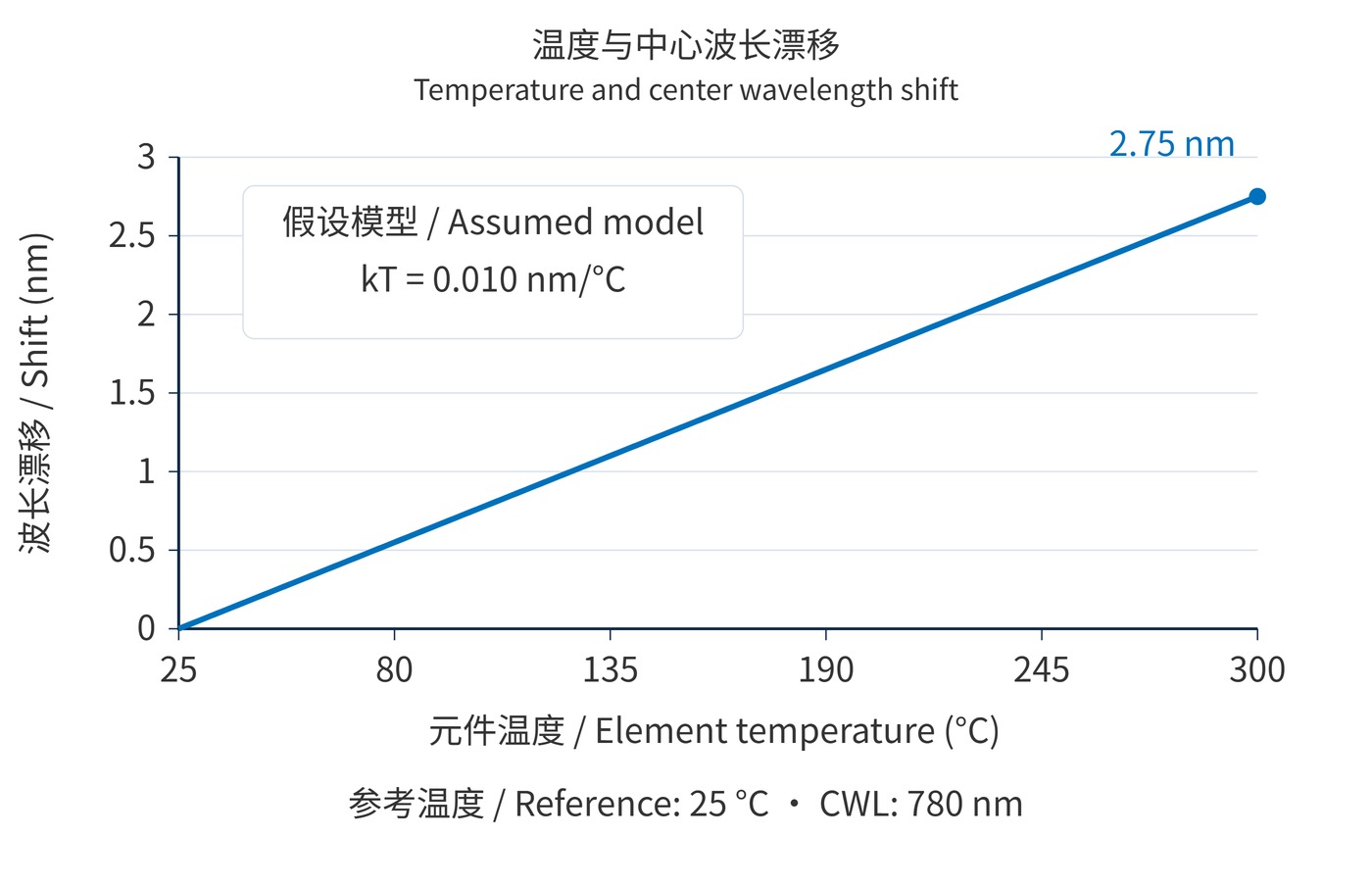
Fig. 2 assumes CWL 780 nm at 25 °C and $k_T=0.010\,\mathrm{nm/^{\circ}C}$. The predicted shift at 300 °C is 2.75 nm. This is a budgeting example, not evidence that a coating survives 300 °C. Real behavior can be nonlinear, with a permanent offset after cooling.
Specify fused silica by grade, rather than simply requesting quartz. Its low expansion helps limit thermal strain, but infrared absorption depends on hydroxyl content, thickness and temperature. Sapphire offers hardness and comparatively good thermal conduction; crystal orientation and expansion mismatch still matter. Neither melting point nor softening point establishes an assembled filter rating.
| Option | Useful starting point | Verify |
|---|---|---|
| Fused silica | Visible/NIR paths and thermal shock | Grade, thickness, hot-state absorption |
| Sapphire | Abrasion resistance and selected MWIR bands | Orientation, long-wave loss, mounting stress |
| Adhesive-free retention | Avoid adhesive softening and outgassing | Clearance, preload, gasket rating and sealing |
Adhesive-free construction still needs compliance. A rigid clamp can generate stress as the metal holder expands differently from the optic. Maintain a defined heat path; increasing thickness can improve stiffness while increasing absorption and thermal gradients.
Review the aperture, illuminated spot size and edge temperature together. Two windows made from the same material can experience very different stress when one is uniformly heated and the other has a concentrated hot spot. A mechanical design must also keep its preload and seal performance through repeated heating and cooling.
An illustrative specification might request CWL 780 nm, FWHM 20 nm, peak transmission ≥85% and OD4 over 400–700 nm at 25 °C and AOI 0°. A proposed 25–300 °C element temperature range then requires separate hot-state drift limits, dwell time, ramp rate and cycle count. These are validation targets, not a product rating. Room-temperature curves in the narrow bandpass filter range are only the starting point.
A receiver observation port can separate the hot atmosphere from a cooler detector path. Reflective rejection also requires a controlled destination for the rejected beam to avoid heating nearby hardware.
Single-band thermometers may operate near 900 nm or 1550 nm, depending on target temperature, emissivity and detector response. For 3000–5000 nm imaging, verify sapphire transmission throughout the actual band at operating temperature, especially its long-wave end. An 8000–14000 nm camera requires a different window material. The infrared band comparison explains these spectral distinctions.
A hot window emits radiation and reflects background radiance as well as transmitting the target signal. Calibrate the complete window–filter–detector path with the actual field of view, and monitor window temperature. The international radiation thermometry guide discusses filter temperature and measurement geometry as sources of spectral response changes.
Keep the target temperature and window temperature as separate calibration inputs. A cooler optical compartment does not eliminate errors from a hot entrance window. Deposits can change its transmission during service, so a calibration performed through a clean, cold window may no longer describe the installed system under load.
Acceptance should report both the operating-temperature spectral error and the residual error after returning to the reference temperature. They constrain different failure mechanisms.
Record the atmosphere and illumination conditions with those results. A successful oven exposure establishes behavior under that exposure; it does not automatically establish performance under concentrated solar flux. Repeatability of the measurement geometry is essential when comparing the initial spectrum with the final one.
 365nm Narrow Bandpass Filter | Ø50mm | T>90%
OT-HBP3659050
365nm Narrow Bandpass Filter; FWHM 10nm; transmission >90%; blocking OD5; size Ø50mm; AOI 0°.
 450nm Narrow Bandpass Filter | Ø50mm
OT-HBP4509050
450nm Narrow Bandpass Filter; FWHM 10nm; transmission >90%; blocking OD5; size Ø50mm; AOI 0°.
 525nm Narrow Bandpass Filter | Ø50mm
OT-HBP5259050
525nm Narrow Bandpass Filter; FWHM 10nm; transmission >90%; blocking OD5; size Ø50mm; AOI 0°.
Send us your drawing and spectral targets — an engineer replies with a feasibility check and quotation within one business day.