Original content by the OOTEE Optics editorial team, drawn from first-hand production line and inspection data. Please credit the source when republishing.
Given limits in expertise and test conditions, the theories, parameters and conclusions here carry no guarantee of absolute accuracy. For technical learning and exchange only - never the sole basis for design, acceptance or selection. Corrections welcome.
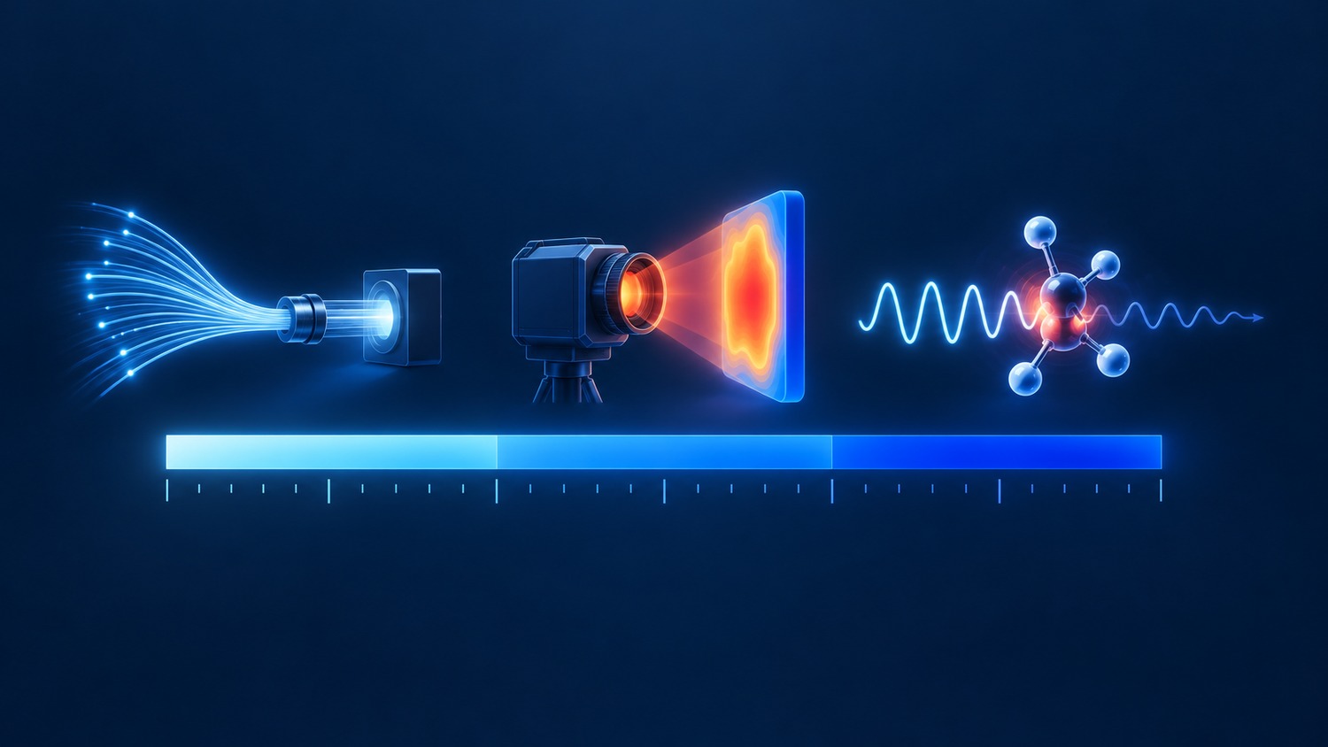
An infrared filter selects useful radiation and suppresses unwanted wavelengths. Its job changes with the measurement: reflected illumination in near infrared, molecular absorption in a gas cell, or thermal emission from a scene. A shared “IR” label does not imply interchangeable filters.
Here, near infrared (NIR) means approximately 780–2500 nm; part of this range is also called shortwave infrared (SWIR). Common thermal imaging windows are 3000–5000 nm for midwave infrared (MWIR) and 8000–14000 nm for longwave infrared (LWIR). These windows are neither contiguous nor three equal divisions of the spectrum.
Mid-infrared (MIR) is broader than MWIR in many conventions. Far infrared (FIR) should not be used as a universal synonym for LWIR: astronomy may place FIR at 30000–1000000 nm. Specify wavelengths instead of relying on names. See the NASA classification and the thermal imager guidance.
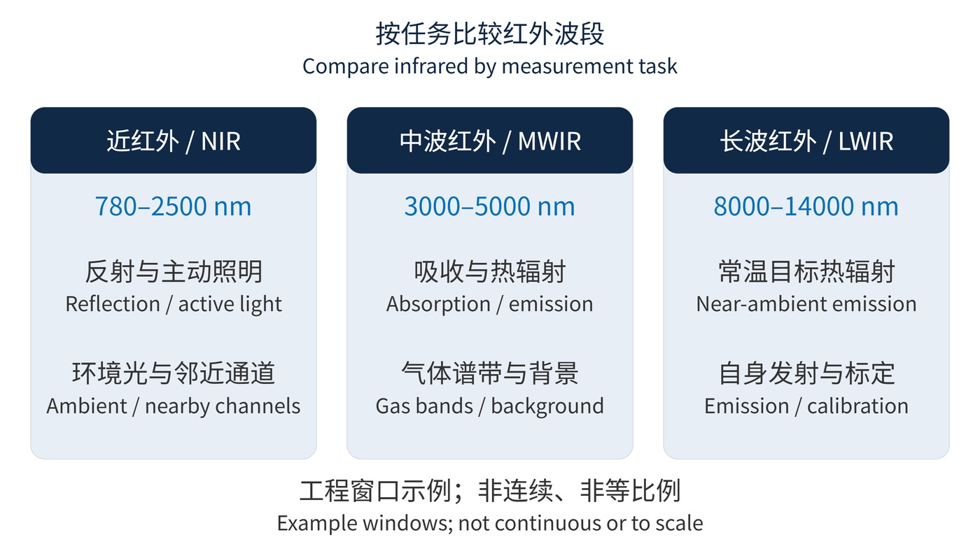
As Fig. 1 shows, background rejection has different meanings in each window. Specify center wavelength (CWL), full width at half maximum (FWHM), optical density (OD) and angle of incidence (AOI) alongside the detector response.
For a simplified linear detection chain, signal current follows the integral below. Here $P_\lambda$ is spectral power density incident on the filter, $T_{\mathrm{sys}}$ includes filter, window and lens transmission, and $R_{\mathrm{d}}$ is detector responsivity. Emission from the optical assembly requires an additional background term.
$$I_{\mathrm{s}}=\int P_\lambda(\lambda)T_{\mathrm{sys}}(\lambda)R_{\mathrm{d}}(\lambda)\,\mathrm{d}\lambda$$
A weak leak can matter when the source is bright outside the passband. Blocking therefore needs a wavelength interval as well as a depth:
$$\mathrm{OD}(\lambda)=-\log_{10}T(\lambda)$$
With transmission expressed as a fraction, OD4 means 0.01%. Thermal backgrounds also become central at longer wavelengths. Wien’s law places the wavelength-domain radiance peak of a 300 K blackbody near 9660 nm; real surfaces introduce emissivity and reflected-background effects.
$$\lambda_{\mathrm{max}}T_{\mathrm{obj}}\approx2.898\times10^6\,\mathrm{nm\,K}$$
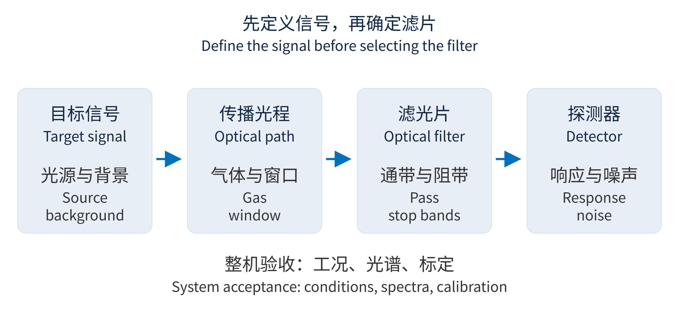
Follow the sequence in Fig. 2. Establish the target spectrum, optical path and detector before choosing a passband. Silicon does not cover every NIR application, and a detector described as cooled or uncooled still needs its actual spectral response checked.
| Window | Example task | Filter priority |
|---|---|---|
| NIR: 940 nm, 1550 nm | Active vision, optical fiber reception | Source and detector matching; ambient and adjacent-channel rejection |
| MWIR: around 4260 nm | Nondispersive carbon dioxide sensing | Absorption band, reference channel and cell path length |
| LWIR: 8000–14000 nm | Thermal imaging near ambient temperature | System transmission, thermal background and calibration |
| FIR: specify the actual interval | Rotational spectroscopy, astronomical detection | Water vapor, detector compatibility and cryogenic design |
Carbon dioxide absorption around 4260 nm supports concentration measurements, as described by NIST. Narrower is not automatically better: it sacrifices flux and increases sensitivity to spectral drift. Pressure, temperature and interfering absorption remain part of the retrieval model.
NIR imaging often records reflected illumination rather than temperature. An atmospheric window is not perfectly transparent: humidity, gas composition and path length still matter. Molecular absorption spans multiple regions, including mid-infrared vibrational bands; it is not exclusive to FIR.
Finally, replacing a filter changes the spectral weighting of a thermal instrument. Existing calibration may no longer apply. For low-contrast targets, background drift from a changing housing temperature can approach the useful signal. Accept the assembly against its wavelength limits, detector-weighted signal and repeatability under operating conditions.
 365nm Narrow Bandpass Filter | Ø50mm | T>90%
OT-HBP3659050
365nm Narrow Bandpass Filter; FWHM 10nm; transmission >90%; blocking OD5; size Ø50mm; AOI 0°.
 450nm Narrow Bandpass Filter | Ø50mm
OT-HBP4509050
450nm Narrow Bandpass Filter; FWHM 10nm; transmission >90%; blocking OD5; size Ø50mm; AOI 0°.
 525nm Narrow Bandpass Filter | Ø50mm
OT-HBP5259050
525nm Narrow Bandpass Filter; FWHM 10nm; transmission >90%; blocking OD5; size Ø50mm; AOI 0°.
Send us your drawing and spectral targets — an engineer replies with a feasibility check and quotation within one business day.