Original content by the OOTEE Optics editorial team, drawn from first-hand production line and inspection data. Please credit the source when republishing.
Given limits in expertise and test conditions, the theories, parameters and conclusions here carry no guarantee of absolute accuracy. For technical learning and exchange only - never the sole basis for design, acceptance or selection. Corrections welcome.

Pre-coating cleaning removes polishing residues, particles, oils and adsorbed contamination. Surface treatment then prepares the surface chemistry and manages adsorbed water as required by the substrate. The objective is a repeatable interface for film nucleation. A visibly clear optic can still carry residues that matter during deposition.
Particles obstruct arriving material; molecular films can create a weak interface or contribute absorption. These require different checks. NASA contamination-control practice treat these as separate categories for the same reason. Appearance alone cannot establish readiness for coating.
Fig. 1 shows why depositing more material does not automatically repair a contaminated interface. Growth around a particle can produce a nodule or a shadowed region. Later particle release may leave a local opening. Residues can also affect bonding, although stress, material compatibility and deposition conditions remain independent contributors to failure.
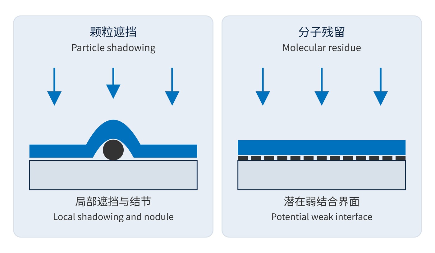
A useful descriptive quantity is projected particle area fraction. For particle areas $a_i$ within clear-aperture area $A$, neglecting overlaps:
$$f=\frac{\sum_i a_i}{A}$$
This is not a scattering-loss equation. Equal area fractions can represent very different particle sizes and distributions. A meaningful specification therefore identifies the aperture, size bins, inspection illumination and magnification.
Deep blocking can be particularly sensitive to local openings. Under uniform illumination and intensity-based area averaging:
$$T_{\mathrm{eff}}=(1-f)T_{\mathrm{film}}+fT_{\mathrm{defect}},\qquad \mathrm{OD}_{\mathrm{eff}}=-\log_{10}T_{\mathrm{eff}}$$
Here $f$ denotes opening area fraction, which can differ from the original particle area fraction. An intact region with optical density (OD) 6 transmits 0.0001%. If $f=10^{-4}$ and an opening is assumed fully transmitting, effective OD falls to approximately 4. This limiting example illustrates leakage sensitivity; it does not predict that each particle creates a clear hole. Beam position and collection geometry affect the measurement.
Start with substrate chemistry, existing coatings, bonded joints and the residue source. Polishing compounds, oils and ionic residues need different removal strategies. Detergents, solvents, rinse water and fixtures can themselves introduce contamination. Ultrasonic frequency, power and mounting require sample validation, especially for thin parts and fragile edges.
| Target | Process concern | Release evidence |
|---|---|---|
| Particles and lint | Removal without scratches or redeposition | Microscopy under defined illumination |
| Organic and ionic residues | Chemical compatibility and rinsing | Witness-coupon analysis and process records |
| Water and surface state | Drying, exposure time and treatment dose | Validated vacuum and treatment windows |
Plasma or ion treatment can assist residue removal and modify the surface, but does not replace upstream cleaning. Excessive treatment may etch, roughen or change material composition. Contact angle on matching witness coupons can track a process trend; it neither proves cleanliness by itself nor provides a universal acceptance angle.
Keep inspection repeatable by fixing the illumination direction, inspected area and reporting method. Record defects by location as well as size, so that a later coating defect can be compared with the original substrate record. A change in particle count is difficult to interpret if the operator also changes the microscope settings or examines a different portion of the aperture.
Fig. 2 includes controlled transfer after inspection. A trial might compare immediate loading with delays of 30 min and 120 min, then assess defects and adhesion. These are experimental groups, not acceptance limits. Interface preparation complements the broader validation discussed under anti-delamination treatment.
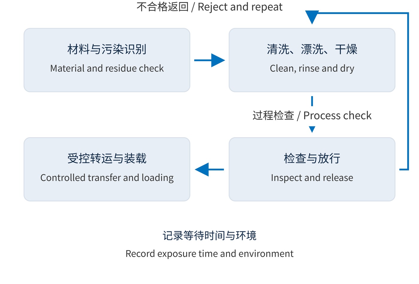
Consider a narrow bandpass filter specified at center wavelength (CWL) 780 nm, full width at half maximum (FWHM) 20 nm and angle of incidence (AOI) 0°, with OD6 blocking over 400–700 nm. This is a requirements example, not a product claim. Specify clear-aperture defect inspection and blocking-test beam size as well: a small beam can miss a local defect.
Weak-fluorescence instruments are sensitive to background and leakage; high-power laser systems also require attention to local absorption and damage initiation. Use relevant wavelengths and operating conditions when validating cleaning. Same-batch witness coupons can support absorption, adhesion or damage tests. Passing a transmission measurement alone does not establish these properties.
For purchasing, separate the optical acceptance limits from the supplier's cleaning recipe. The customer needs reproducible evidence at the specified aperture and test geometry; the manufacturer needs a qualified process for the particular material. When a detergent, rinse sequence, fixture or storage interval changes, compare the affected results with the established baseline before treating the revised sequence as equivalent.
A traceable process connects contaminant type, treatment window and release evidence. Defined inspection conditions and exposure limits make defects easier to investigate than a general instruction to clean thoroughly.
Retain the inspection and loading records with the coating batch. If an issue appears later, these records help distinguish a persistent substrate defect from contamination introduced during transfer or a problem created during deposition.
 365nm Narrow Bandpass Filter | Ø50mm | T>90%
OT-HBP3659050
365nm Narrow Bandpass Filter; FWHM 10nm; transmission >90%; blocking OD5; size Ø50mm; AOI 0°.
 450nm Narrow Bandpass Filter | Ø50mm
OT-HBP4509050
450nm Narrow Bandpass Filter; FWHM 10nm; transmission >90%; blocking OD5; size Ø50mm; AOI 0°.
 525nm Narrow Bandpass Filter | Ø50mm
OT-HBP5259050
525nm Narrow Bandpass Filter; FWHM 10nm; transmission >90%; blocking OD5; size Ø50mm; AOI 0°.
Send us your drawing and spectral targets — an engineer replies with a feasibility check and quotation within one business day.