Original content by the OOTEE Optics editorial team, drawn from first-hand production line and inspection data. Please credit the source when republishing.
Given limits in expertise and test conditions, the theories, parameters and conclusions here carry no guarantee of absolute accuracy. For technical learning and exchange only - never the sole basis for design, acceptance or selection. Corrections welcome.
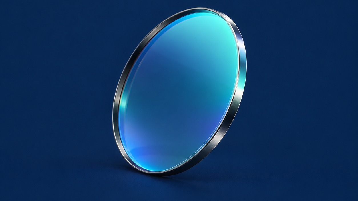
A LiDAR bandpass filter admits the laser return while attenuating out-of-band sunlight and stray light. In a pulsed time-of-flight receiver, its practical value is preserving weak returns without exhausting detector dynamic range. The narrowest available passband is not automatically the best choice.
Common architectures use 905 nm with silicon detectors or 1550 nm with indium gallium arsenide detectors. Their spectral responses differ, so the blocking specification must change with the receiver. All numerical requirements below are illustrative engineering targets, not product guarantees.
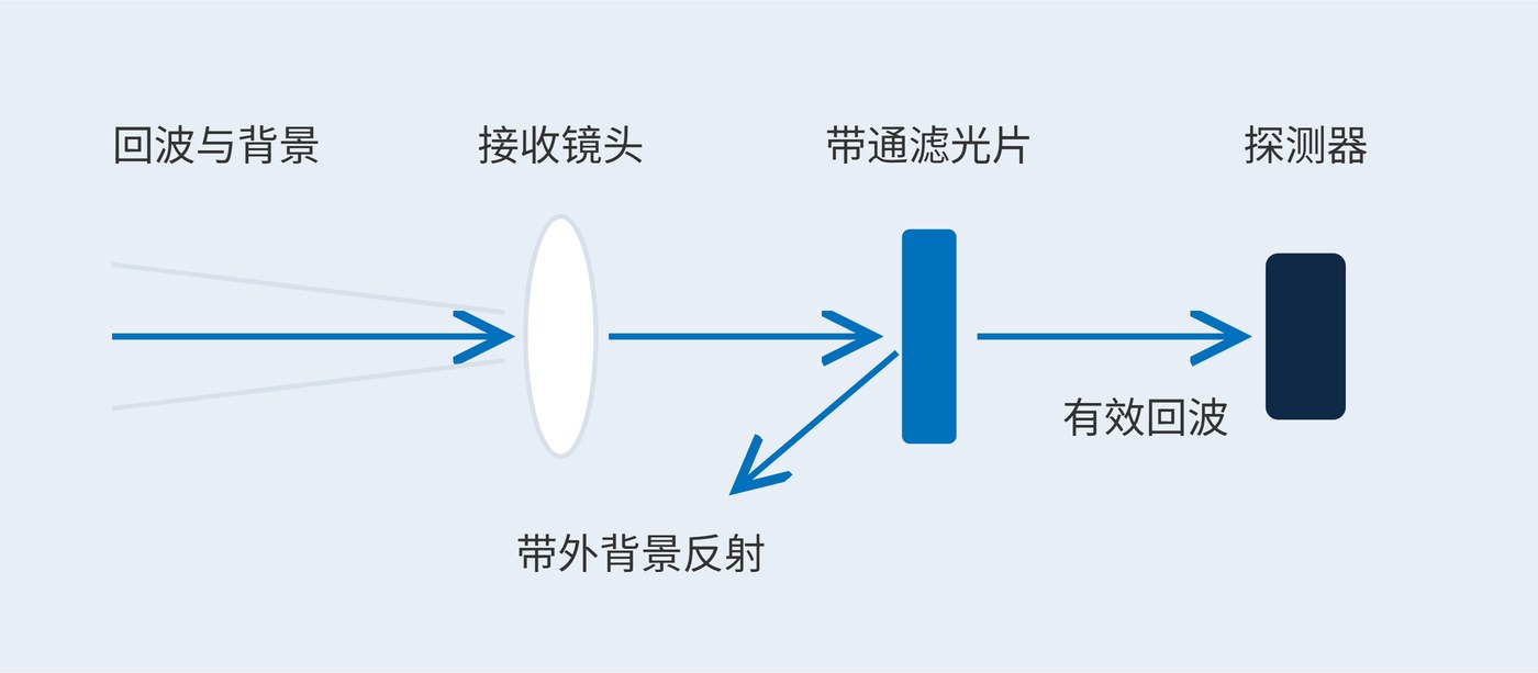
Thin-film interference creates a transmission window. Fig. 1 shows its location in the receive path; light bypassing the filter still requires mechanical baffling. Center wavelength (CWL) locates the window, while full width at half maximum (FWHM) describes its width at half the peak transmission. FWHM is not a guaranteed high-transmission interval.
Optical density (OD) specifies attenuation using dimensionless transmittance $T$. OD6 means a transmitted fraction of $10^{-6}$, or 0.0001%, within a stated blocking range.
$$\mathrm{OD}(\lambda)=-\log_{10}T(\lambda)$$
Increasing angle of incidence (AOI) generally shifts an interference passband toward shorter wavelengths. An effective-index approximation supports an initial budget:
$$\lambda(\theta)\approx\lambda(0)\sqrt{1-\frac{\sin^2\theta}{n_{\mathrm{eff}}^2}}$$
With $n_{\mathrm{eff}}=2.0$, a 905 nm normal-incidence center shifts to about 901.6 nm at 10°. Actual coating behavior, polarization splitting and converging beams require measurement. Trace both chief and marginal rays at the filter: receiver field of view alone does not specify AOI.
Measure the laser spectrum across temperature, drive current and pulse conditions. Then include filter tolerances and angular shifts. Fig. 2 isolates the bandwidth trade-off: both ideal curves have the same center and peak, but a narrow window loses transmission faster when the return wavelength moves.
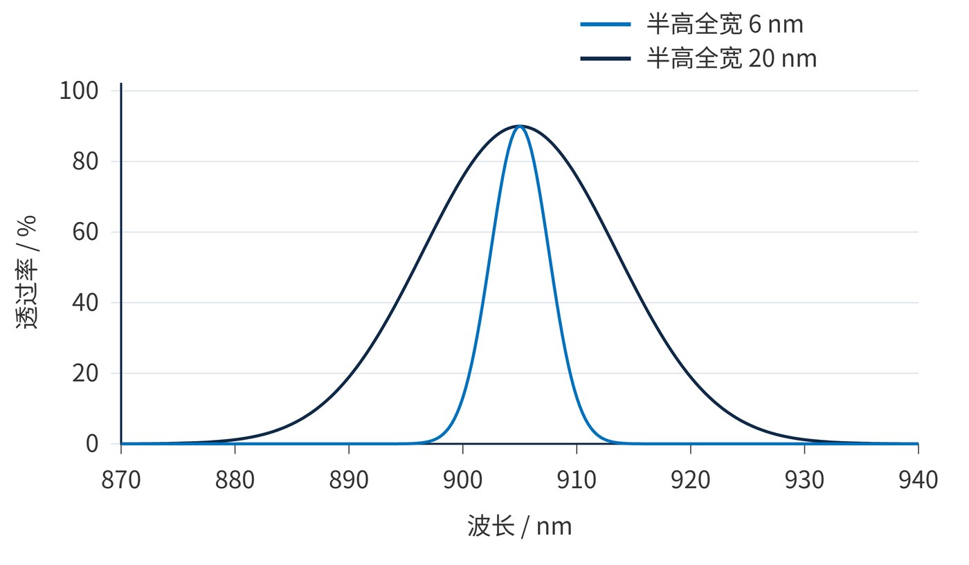
For a hypothetical laser envelope of 902–908 nm, start by requiring at least 85% transmission throughout that interval under the agreed operating conditions. Only then assess a nominal CWL of 905 nm and FWHM of 20 nm. Several nanometers of angular shift may justify a pre-offset center or a different filter location.
| Budget item | Illustrative requirement | Purpose |
|---|---|---|
| Useful return | ≥85% across 902–908 nm at operating extremes | Protect return throughput |
| Angle and temperature | AOI 0–10°; −20 to 70 °C | Check combined extremes |
| Blocking | OD ≥5 over 400–880 nm and 930–1100 nm | Starting point for a silicon receiver |
| Assembly and test | Clear aperture, thickness tolerance, test spot and polarization | Make acceptance reproducible |
These targets require a feasibility review. Specify transition regions between blocking and transmission; an OD5 requirement cannot extend directly to a high-transmission boundary. A 1550 nm receiver needs blocking limits based on its own detector response.
Ask for transmission at the actual laser wavelengths rather than relying on nominal bandwidth. In the ideal 20 nm Gaussian example, transmission at 902 nm and 908 nm is about 84.6%, already below the illustrative 85% requirement even before angular or manufacturing effects. A flatter passband, additional width or revised optical geometry may therefore be needed. This is why a nominal CWL and FWHM pair cannot replace an interval-based throughput requirement.
For sample evaluation, record the measurement spot, spectral resolution and incident polarization alongside each curve. Use the same conditions when comparing samples, and distinguish guaranteed limits from typical data. Include assembly tolerances when deciding which angular and temperature combinations represent the operating extremes.
Background rejection depends on integrated leakage, not one OD value. For background spectral irradiance $E_{\mathrm{bg}}$ at the filter, effective collection area $A$ and detector responsivity $\mathcal{R}$, the approximate background photocurrent is:
$$I_{\mathrm{bg}}=A\int E_{\mathrm{bg}}(\lambda)T(\lambda)\mathcal{R}(\lambda)\,\mathrm{d}\lambda$$
Use consistent spectral units, such as irradiance per nm with integration in nm. A square-root bandwidth benefit applies when background shot noise dominates, the background spectrum is locally flat and signal throughput stays constant. It does not directly describe dark-noise-limited or saturated operation.
A long-range vehicle receiver must retain weak returns under strong daylight, including at field edges. Outdoor robots also need checks for window tilt, scattering and light bypass. Wide-field detector arrays require transmission assessment across the image plane because pixels can see different incidence angles.
A narrow-field industrial rangefinder with controlled angles and limited laser drift may support a narrower passband. A wide-field design may benefit more from angular tolerance or optical relocation. Coherent receivers introduce local-oscillator and polarization constraints beyond this pulsed-receiver example.
Technical reference: LiDAR source and detector pairing. Acceptance should link spectral measurements to return signal, background current, saturation margin and false-trigger results in the actual receive path.
 365nm Narrow Bandpass Filter | Ø50mm | T>90%
OT-HBP3659050
365nm Narrow Bandpass Filter; FWHM 10nm; transmission >90%; blocking OD5; size Ø50mm; AOI 0°.
 450nm Narrow Bandpass Filter | Ø50mm
OT-HBP4509050
450nm Narrow Bandpass Filter; FWHM 10nm; transmission >90%; blocking OD5; size Ø50mm; AOI 0°.
 525nm Narrow Bandpass Filter | Ø50mm
OT-HBP5259050
525nm Narrow Bandpass Filter; FWHM 10nm; transmission >90%; blocking OD5; size Ø50mm; AOI 0°.
Send us your drawing and spectral targets — an engineer replies with a feasibility check and quotation within one business day.