Original content by the OOTEE Optics editorial team, drawn from first-hand production line and inspection data. Please credit the source when republishing.
Given limits in expertise and test conditions, the theories, parameters and conclusions here carry no guarantee of absolute accuracy. For technical learning and exchange only - never the sole basis for design, acceptance or selection. Corrections welcome.

A longpass (LP) filter rejects shorter wavelengths and transmits longer wavelengths within its specified operating range, following the introductory filter material in the Florida State University microscopy primer. The change between those regions takes a finite wavelength interval. “Edge slope” may describe a rate of change or the width of that interval. A sharper edge gives a larger rate but a smaller width, so a number without its definition is ambiguous.
Let $T_{\mathrm{p}}$ be a stated passband reference transmission and define normalized transmission as $t=T/T_{\mathrm{p}}$. For relative 10% and 90% endpoints:
$$\Delta\lambda_{10-90}=\lambda_{90}-\lambda_{10},\qquad \bar{s}=\frac{0.8}{\Delta\lambda_{10-90}}$$
The average rate has units of $\mathrm{nm}^{-1}$ when wavelength is in nm. Transmission here is a fraction, so the numerator is 0.8. The reference transmission and the wavelength range used to establish it must also be stated.
Interference in a dielectric coating produces the spectral edge. Figure 1 isolates the effect of transition width using an analytical model: only the width changes. These are illustrative calculations, not measured filters or coating designs.
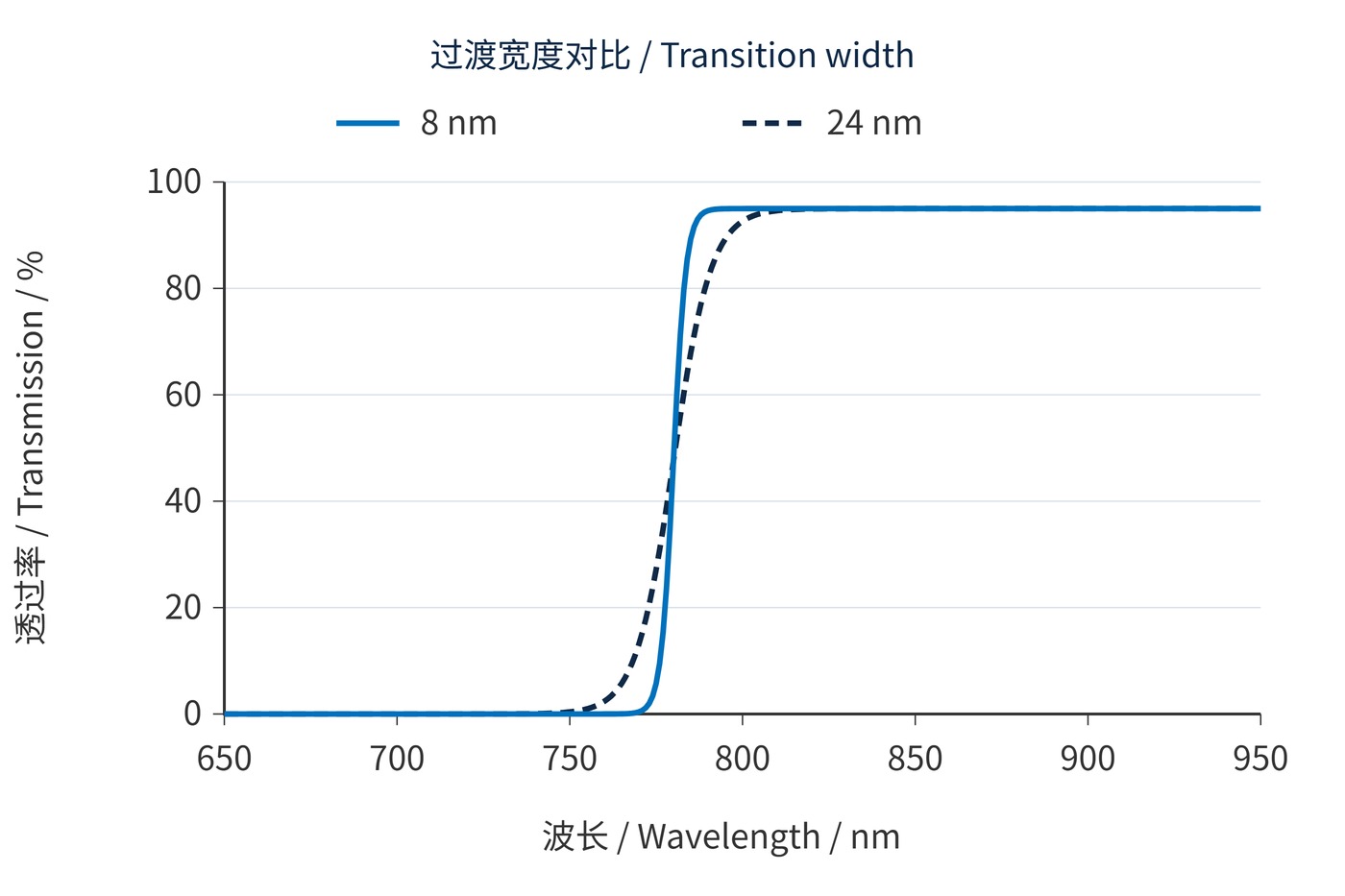
Relative midpoint 780 nm; reference transmission 95%; floor 10⁻⁸; normal incidence; analytical model sampled at 1 nm.
The floor-limited logistic model uses $T_{\mathrm{min}}=10^{-8}$ and $T_{\mathrm{p}}=0.95$. Parameters $a$ and $\lambda_{\mathrm{c}}$ are solved to preserve the relative midpoint and the specified width:
$$T(\lambda)=T_{\mathrm{min}}+\frac{T_{\mathrm{p}}-T_{\mathrm{min}}}{1+\exp[-(\lambda-\lambda_{\mathrm{c}})/a]}$$
Both curves cross relative 50% transmission at 780 nm and approach a 95% passband. Their relative 10%–90% widths are 8 nm and 24 nm. A cut-on wavelength alone therefore cannot predict how much nearby signal will pass.
Relative and absolute thresholds also differ. With a 95% reference, relative 90% means absolute 85.5%; relative 50% means absolute 47.5%. An absolute 50% cut-on lies at a slightly different wavelength. A width expressed as a percentage needs a named denominator: 8 nm divided by 780 nm is approximately 1.03%.
Optical density (OD) uses absolute transmission $T$ as a fraction:
$$\mathrm{OD}(\lambda)=-\log_{10}T(\lambda)$$
OD6 means a transmission of $10^{-6}$, or 0.0001%. A relative 10%–90% measurement never reaches that tail. In Figure 2, the narrow-edge model still needs approximately 29.1 nm to rise from OD6 to relative 90%, although its 10%–90% width is only 8 nm.
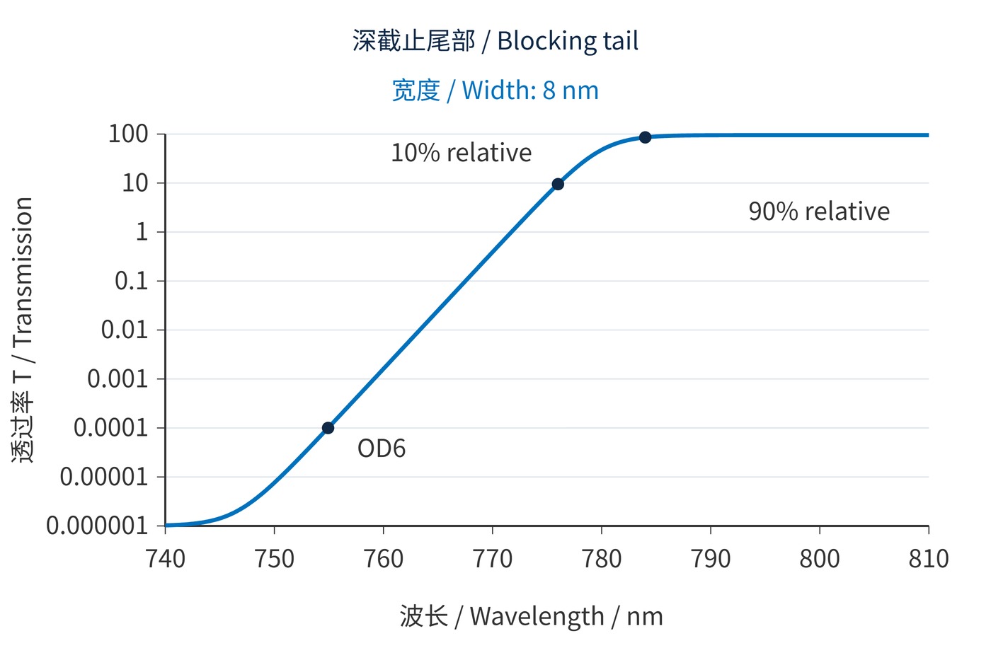
Relative midpoint 780 nm; reference transmission 95%; width 8 nm; floor 10⁻⁸; normal incidence; analytical model sampled at 0.1 nm.
Identify the longest wavelength that must be rejected and the shortest that must pass. Reserve margin for edge-position tolerance, angle of incidence (AOI), temperature and beam cone angle. The following is a requirements example, not a product specification or a statement of availability.
| Item | Example requirement | Acceptance meaning |
|---|---|---|
| Stopband | 400–750 nm, OD ≥ 6 | Pointwise requirement across the range |
| Passband | 800–1000 nm, T ≥ 90% | Minimum absolute transmission |
| Edge position | 780 ± 2 nm at absolute T = 50% | Separate from normalized thresholds |
| Operating conditions | AOI 0° ± 1°, 23 ± 2 °C | Also define polarization, cone angle and clear aperture |
If edge shape matters, add a relative 10%–90% width of ≤ 8 nm and a separate maximum interval from OD6 to absolute 90% transmission. Verify both. A longpass filter has no inherent symmetric passband center: center wavelength (CWL) and full width at half maximum (FWHM) do not replace its edge specifications.
Request both scan increment and instrument spectral bandwidth. An increment of ≤ 1 nm is a useful starting point for sampling an 8 nm edge, but fine sampling cannot overcome broad instrument bandwidth. OD6 measurements additionally need sufficient dynamic range and stray-light control. A result below the detection limit is a bound, not an exact transmission value.
In fluorescence detection, closely spaced excitation and emission require joint limits on excitation blocking and transmission at the beginning of the emission band. Raman systems need rejection at the laser line and adequate transmission at the target Stokes wavelengths. A steep middle section alone does not establish access to small Raman shifts.
Machine vision that separates widely spaced visible and near-infrared bands may gain little from an exceptionally narrow transition. Evaluate the source, target spectrum and detector response together. Neither maximum transmission nor edge sharpness alone determines system signal-to-noise ratio.
A usable LP edge specification fixes the thresholds, normalization, reference wavelength and test conditions, while pointwise stopband and passband limits constrain performance on either side.
 365nm Narrow Bandpass Filter | Ø50mm | T>90%
OT-HBP3659050
365nm Narrow Bandpass Filter; FWHM 10nm; transmission >90%; blocking OD5; size Ø50mm; AOI 0°.
 450nm Narrow Bandpass Filter | Ø50mm
OT-HBP4509050
450nm Narrow Bandpass Filter; FWHM 10nm; transmission >90%; blocking OD5; size Ø50mm; AOI 0°.
 525nm Narrow Bandpass Filter | Ø50mm
OT-HBP5259050
525nm Narrow Bandpass Filter; FWHM 10nm; transmission >90%; blocking OD5; size Ø50mm; AOI 0°.
Send us your drawing and spectral targets — an engineer replies with a feasibility check and quotation within one business day.