Original content by the OOTEE Optics editorial team, drawn from first-hand production line and inspection data. Please credit the source when republishing.
Given limits in expertise and test conditions, the theories, parameters and conclusions here carry no guarantee of absolute accuracy. For technical learning and exchange only - never the sole basis for design, acceptance or selection. Corrections welcome.

A machine vision filter selects the wavelength, polarization state or intensity reaching the camera. Its purpose is stable separation between a defect and its background across parts and operating conditions. A monochrome sensor still has a wavelength-dependent response.
Start with representative good and defective parts. Establish useful lighting geometry and wavelength before choosing a filter. With an existing illuminator, measure its spectrum at operating temperature first. Filtering cannot create a scratch signal that the lighting geometry never produced.
Center wavelength (CWL) locates a passband. Full width at half maximum (FWHM) is the distance between its half-peak edges, not a one-sided half-width. Optical density (OD) describes attenuation; angle of incidence (AOI) affects the position of an interference passband. A light-emitting diode (LED) needs a measured spectrum, not just a nominal wavelength.
For fractional transmittance $T$:
$$\mathrm{OD}(\lambda)=-\log_{10}T(\lambda)$$
OD3 means 0.1% transmission within the specified blocking range. A near-infrared leak can still reach a sensitive sensor even when visible blocking is adequate.
At fixed exposure, a linear, unsaturated pixel signal can be approximated by:
$$S_i=K\int E(\lambda)\rho_i(\lambda)T(\lambda)Q(\lambda)\,\mathrm{d}\lambda$$
Here $E$ is illumination at the part, $\rho_i$ its effective reflectance for the chosen geometry, and $Q$ camera response. $K$ includes exposure and imaging scale. Ambient illumination is a separate contribution. Similar defect and background spectra mean that spectral filtering may reject interference without increasing their intrinsic contrast.
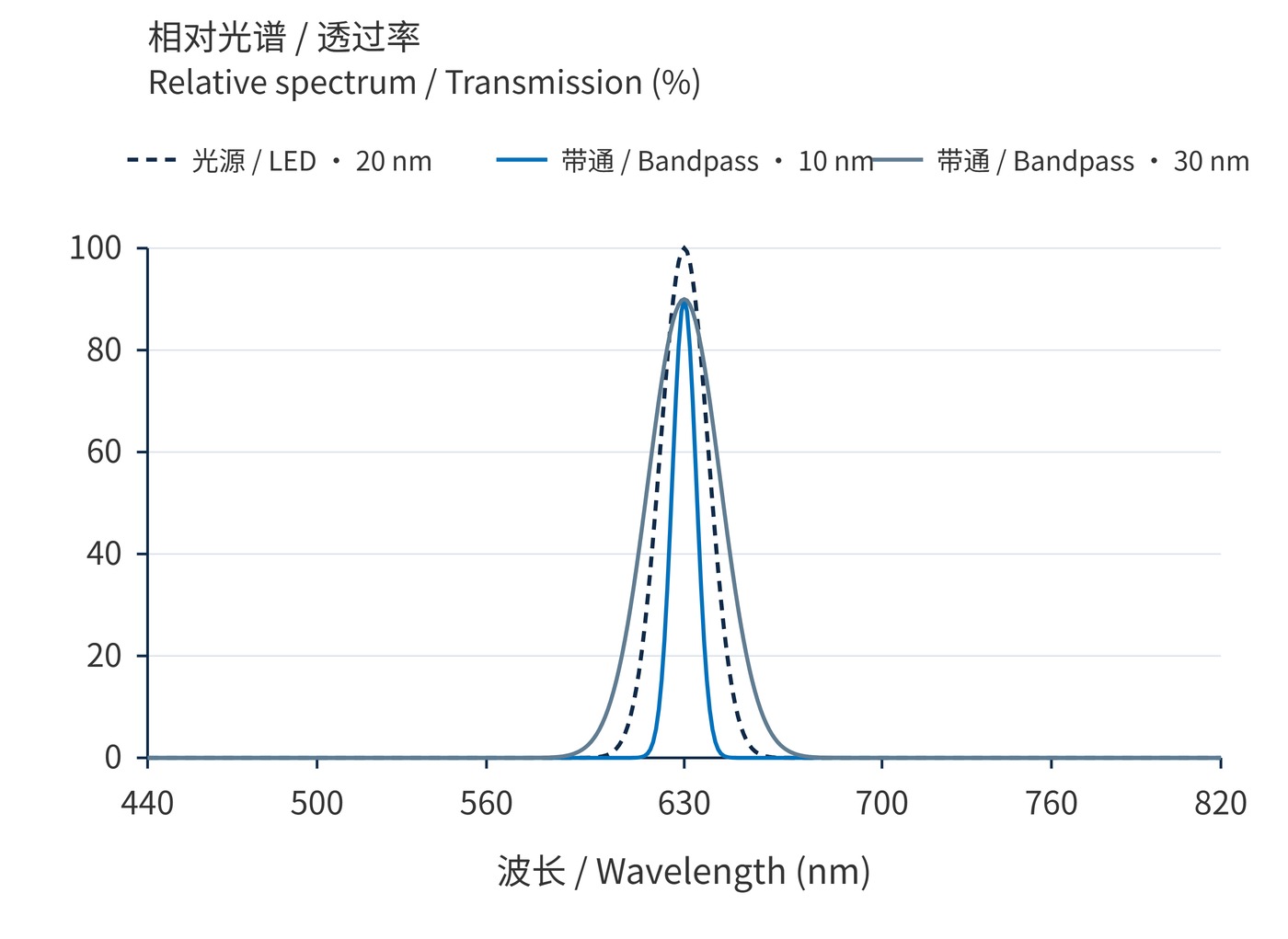
In Fig. 1, the LED has 20 nm FWHM. Both filters have CWL 630 nm and 90% peak transmission. Integration at 1 nm intervals gives approximately 40% LED energy throughput for the 10 nm filter and 75% for the 30 nm filter. These are mathematical examples; measured flat-top passbands require a fresh calculation.
Compare defect separation under candidate illumination wavelengths, then establish the exposure budget. When specifying a bandpass filter, include LED bin variation, heating, CWL tolerance and the angles of marginal rays. Matching filter FWHM to LED FWHM does not transmit all useful light.
| Symptom | First approach | Verify |
|---|---|---|
| Ambient light changes monochrome images | Bandpass matched to illumination | Signal margin across the field |
| Glare on glass or metal | Adjust geometry, then test crossed polarization | Defect signal as well as glare |
| Overall saturation | Reduce light or exposure, then consider ND | Bright regions and faint defects |
A trial specification might use CWL 630 nm, FWHM 30 nm, peak transmission at least 90%, and OD3 blocking over 400–600 nm and 660–1000 nm. Define AOI, clear aperture and transition regions before procurement; this is a starting point for testing.
Ask for transmission data across the sensor's useful range, including any secondary passbands. Compare the dimmest acceptable defect with the brightest normal surface at the required cycle time. A filter that produces a cleaner image at long exposure may leave too little signal for a moving production line.
Crossed polarization uses a source polarizer and a lens analyzer, initially 90° apart. Glass glare often responds well. Bare metal, curved parts and rough surfaces require testing because reflection can change polarization. If scratches fade with the glare, change geometry or relax the crossing angle.
A neutral density filter (ND) helps when exposure or aperture must stay fixed. OD0.6 transmits about 25%, reducing linear signal to roughly one quarter. It also attenuates faint defects rather than selectively removing glare. Check spectral flatness over the working band.
Bandpass filtering can stabilize monochrome mark inspection against ambient light. Glass inspection often starts with glare control. Metal scratches first need useful scattering contrast. Follow Fig. 2 while changing one main factor per trial.
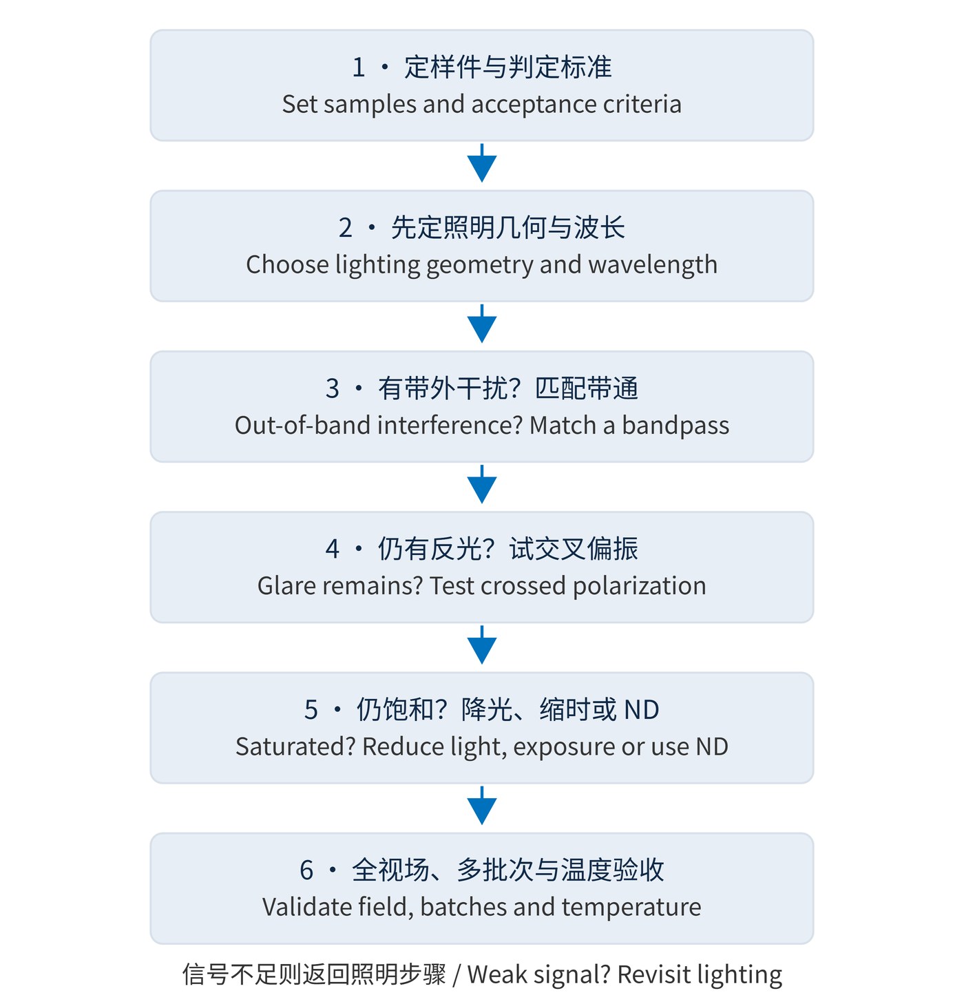
A narrower bandpass can waste photons and increase sensitivity to wavelength shifts. Deeper blocking cannot remove glare at the illumination wavelength. A rotating analyzer alone is also different from a complete crossed-polarization arrangement.
Hold exposure, gain and processing fixed during comparisons. Record saturation, defect separation and noise with automatic exposure disabled. Accept the system against missed defects, false rejects and cycle time on an agreed sample set, retaining raw images from the worst temperature, pose and ambient-light conditions.
Include scratches near the acceptance limit rather than testing only obvious damage. Rotate representative parts to expose directional machining marks and specular highlights. After any filter change, check focus and field uniformity again: additional glass and restricted apertures can affect imaging as well as brightness. Record the final mechanical arrangement so that subsequent assemblies reproduce the tested geometry. Repeat acceptance checks after replacing the illuminator with a different production batch.
 365nm Narrow Bandpass Filter | Ø50mm | T>90%
OT-HBP3659050
365nm Narrow Bandpass Filter; FWHM 10nm; transmission >90%; blocking OD5; size Ø50mm; AOI 0°.
 450nm Narrow Bandpass Filter | Ø50mm
OT-HBP4509050
450nm Narrow Bandpass Filter; FWHM 10nm; transmission >90%; blocking OD5; size Ø50mm; AOI 0°.
 525nm Narrow Bandpass Filter | Ø50mm
OT-HBP5259050
525nm Narrow Bandpass Filter; FWHM 10nm; transmission >90%; blocking OD5; size Ø50mm; AOI 0°.
Send us your drawing and spectral targets — an engineer replies with a feasibility check and quotation within one business day.