Original content by the OOTEE Optics editorial team, drawn from first-hand production line and inspection data. Please credit the source when republishing.
Given limits in expertise and test conditions, the theories, parameters and conclusions here carry no guarantee of absolute accuracy. For technical learning and exchange only - never the sole basis for design, acceptance or selection. Corrections welcome.

Magnetron sputtering deposits optical coatings by bombarding a target with ions. Argon is introduced into a vacuum chamber and ionized in a discharge. Positive ions accelerate toward the target, ejecting atoms that can travel to a substrate and form a film. Magnets behind the target confine electrons near its surface, sustaining a dense local plasma and producing the familiar racetrack erosion zone.
Optical filters use alternating materials with different refractive indices. In reactive sputtering from metallic targets, oxygen or another reactive gas helps form the required compound. As Fig. 1 shows, incoming ions and outgoing coating material travel in different directions. The magnetic field primarily confines electrons; it does not pull the coating onto the glass.
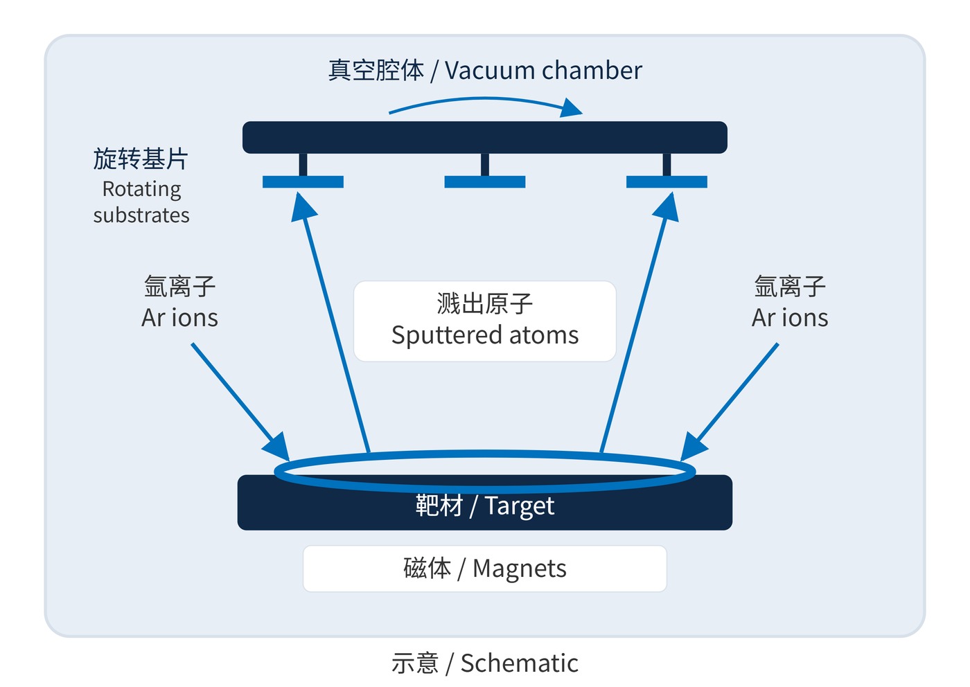
The practical advantage is a repeatable deposition process combining power control, gas regulation, substrate motion and thickness monitoring. Suitable conditions can produce dense films with reduced sensitivity to moisture uptake. Low absorption, low scatter and acceptable stress still require separate optimization; none follows automatically from the process name.
Both refractive index and physical thickness determine optical thickness. A quarter-wave layer at normal incidence follows:
$$n d = \frac{\lambda_0}{4}$$
At a design wavelength of 780 nm, illustrative indices of 2.10 and 1.45 give thicknesses of approximately 92.9 nm and 134.5 nm. These are layer examples, not a complete bandpass design. The actual index depends on wavelength, composition and deposition conditions.
If every layer experiences approximately the same fractional optical-thickness change, and dispersion changes are neglected, a first-order estimate is:
$$\frac{\Delta\lambda}{\lambda_0}\approx\frac{\Delta(n d)}{n d}\approx\frac{\Delta n}{n}+\frac{\Delta d}{d}$$
A uniform 0.1% increase would shift a feature near 780 nm toward longer wavelengths by about 0.78 nm. Random layer errors can instead distort the passband or introduce ripple. Reactive sputtering adds another challenge: target oxidation creates hysteresis, so identical oxygen flow settings need not produce identical rates or compositions. Appropriate feedback is therefore essential.
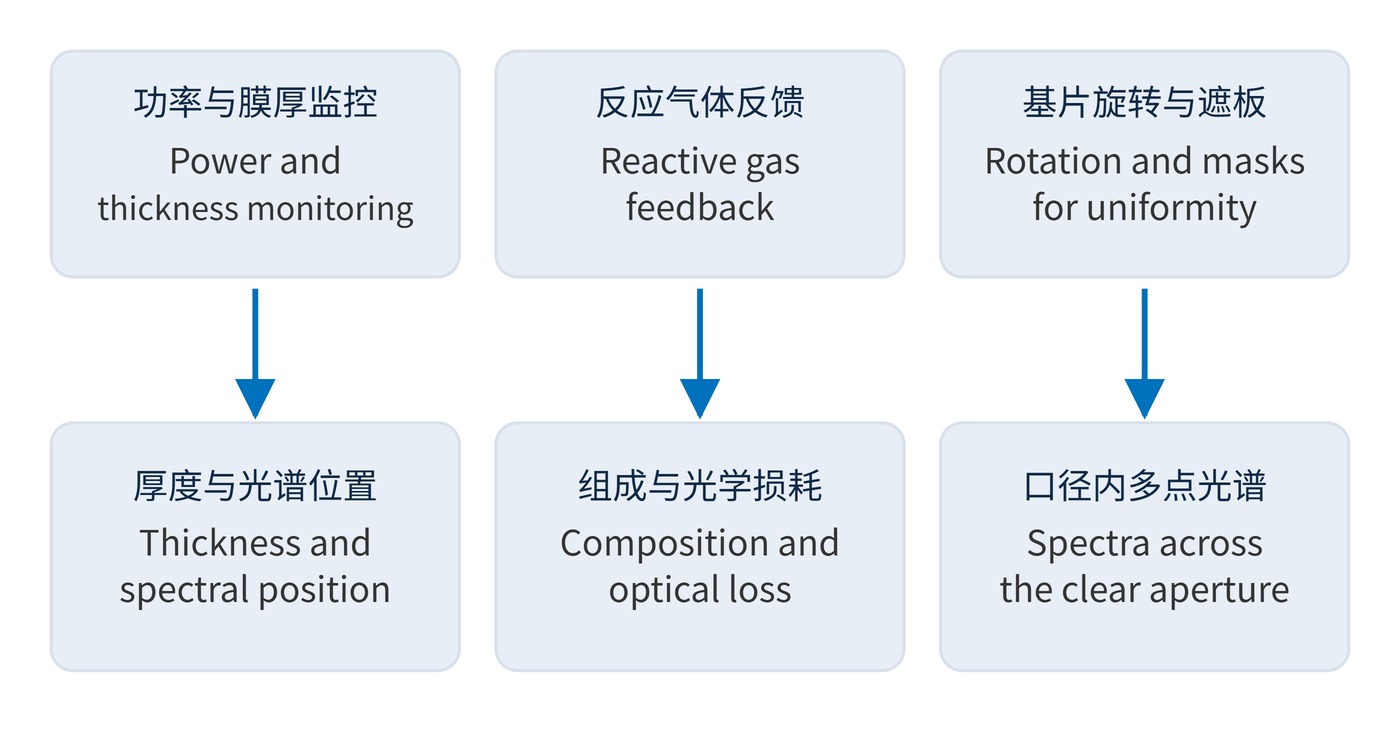
Start with center wavelength (CWL), full width at half maximum (FWHM), optical density (OD) and angle of incidence (AOI). Then evaluate whether the process delivers them across the required aperture and production quantity. Fig. 2 separates three control tasks: thickness, composition and spatial uniformity. Increasing deposition time cannot correct all three.
| Property | Illustrative requirement | Evidence to request |
|---|---|---|
| Passband position | CWL 780 ± 1 nm; FWHM 20 ± 2 nm | Measured spectrum at AOI 0° and 23 °C |
| Transmission and blocking | Minimum transmission ≥90% over 775–785 nm; OD6 over 400–740 nm and 820–1000 nm | Separate passband and blocking measurements with stated dynamic range and stray-light control |
| Spatial consistency | Maximum CWL difference ≤1 nm across a 20 mm clear aperture | Center and edge measurements with beam size specified |
| Environmental retention | Agree drift limits for system temperature and humidity conditions | Spectra, appearance and surface figure before and after testing |
These numbers illustrate a specification and are not product guarantees. A trace close to zero on an ordinary scan does not establish OD6:
$$\mathrm{OD}=-\log_{10}T,\qquad \mathrm{OD}=6\Rightarrow T=10^{-6}=0.0001\%$$
Use fractional transmittance in the logarithm. Agree sampling rules and coated surface-figure limits as well. Residual coating stress can bend thin substrates. Rotation averages some deposition differences but does not by itself guarantee uniformity over the clear aperture.
Record whether each reported result represents one location, an aperture average or the worst measured point.
In multichannel fluorescence instruments, repeatable optical thickness helps maintain edge positions and channel separation. Laser receivers benefit when a coating consistently combines signal transmission with specified background rejection. Acceptance must still include blocking ranges, beam cone angles and polarization: sputtering does not remove the angular response of an interference filter.
For recurring industrial inspection orders, automated process records help investigate batch changes. Useful evidence includes spectra from several loading positions and production batches. A single sample's peak transmission cannot demonstrate production capability. Large or thin optics additionally require joint assessment of uniformity, stress and mounting conditions.
The same logic applies when moving from prototypes to a full production load. Substrate packing, target erosion and the maintenance state can change the deposition environment. A qualified process should connect those changes to measurable acceptance results. For procurement, retaining the measurement geometry and environmental conditions alongside each spectrum makes later comparisons meaningful. If a replacement batch appears shifted, first compare the test conditions and aperture locations before attributing the difference to the coating recipe.
Technical background is available from institutions such as Fraunhofer IOF on precision optical deposition, together with published tutorials on reactive-sputtering hysteresis. The meaningful outcome is reproducible spectral performance and stability over a defined aperture under stated conditions.
 365nm Narrow Bandpass Filter | Ø50mm | T>90%
OT-HBP3659050
365nm Narrow Bandpass Filter; FWHM 10nm; transmission >90%; blocking OD5; size Ø50mm; AOI 0°.
 450nm Narrow Bandpass Filter | Ø50mm
OT-HBP4509050
450nm Narrow Bandpass Filter; FWHM 10nm; transmission >90%; blocking OD5; size Ø50mm; AOI 0°.
 525nm Narrow Bandpass Filter | Ø50mm
OT-HBP5259050
525nm Narrow Bandpass Filter; FWHM 10nm; transmission >90%; blocking OD5; size Ø50mm; AOI 0°.
Send us your drawing and spectral targets — an engineer replies with a feasibility check and quotation within one business day.