Original content by the OOTEE Optics editorial team, drawn from first-hand production line and inspection data. Please credit the source when republishing.
Given limits in expertise and test conditions, the theories, parameters and conclusions here carry no guarantee of absolute accuracy. For technical learning and exchange only - never the sole basis for design, acceptance or selection. Corrections welcome.
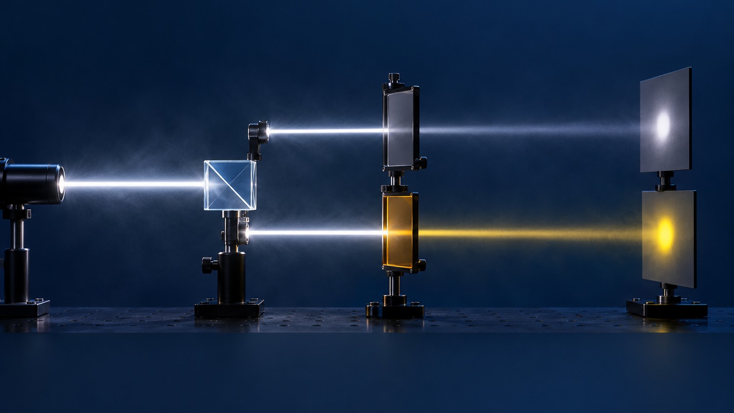
A neutral density (ND) filter reduces optical power by approximately the same fraction across a specified wavelength range. Ideally, it changes the amplitude of a spectrum while preserving its shape. White light becomes dimmer with little change in chromaticity or color temperature; a laser receives a predictable attenuation at its operating wavelength.
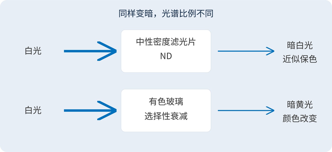
Neutrality is a specification over a defined band, not a promise at every wavelength. Color temperature alone cannot describe every tint, and it is generally inappropriate for nonwhite sources. Fig. 1 contrasts neutral attenuation with the wavelength-selective attenuation of colored glass.
Optical density (OD) expresses attenuation logarithmically. In the following definition, transmittance $T$ is a fraction between 0 and 1, not a percentage:
$$\mathrm{OD}(\lambda)=-\log_{10}T(\lambda),\qquad T(\lambda)=\frac{P_{\mathrm{out}}(\lambda)}{P_{\mathrm{in}}(\lambda)}$$
| Optical density / OD | Transmittance / % | Attenuation factor |
|---|---|---|
| 0.3 | Approximately 50.1 | Approximately 2 |
| 1 | 10 | 10 |
| 2 | 1 | 100 |
| 3 | 0.1 | 1000 |
Absorptive filters dissipate much of the rejected power as heat. Reflective filters redirect more of it, although absorption and heating can remain significant. With negligible scattering and consistent wavelength and collection conditions, transmittance, reflectance and absorptance obey:
$$T+R+A=1$$
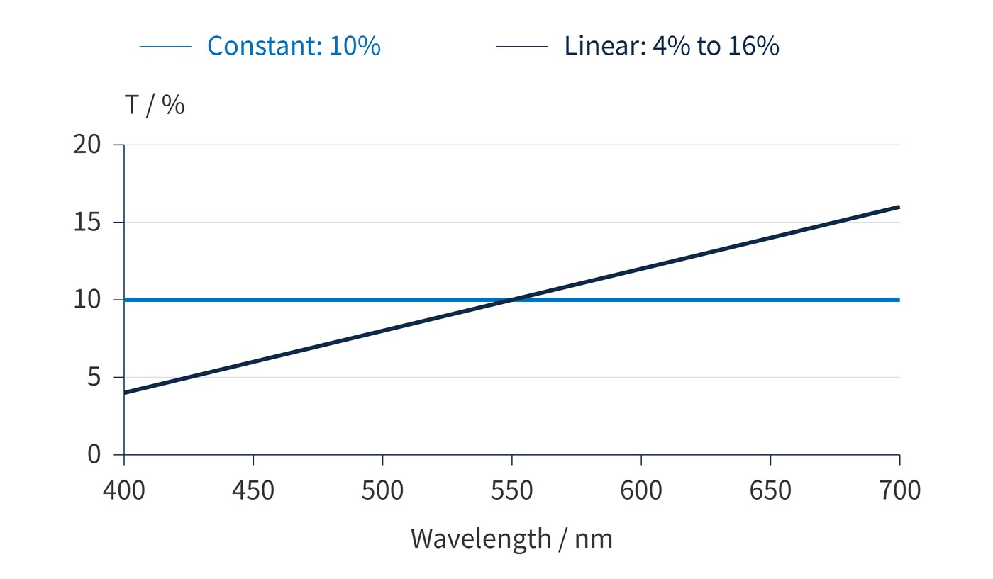
A single OD value says little about spectral neutrality. Two filters can both have OD1 at 550 nm yet attenuate blue and red light differently. Fig. 2 isolates this distinction using a constant transmission model and a sloping model with the same reference-point value.
Start with the maximum incident power and the detector's linear operating range. Reducing 2 mW to no more than 20 μW requires at least 100-fold attenuation, or OD2. Allow additional margin for source fluctuations, using powers measured with consistent apertures and collection geometry.
An example requirement is 400–700 nm operation, OD1.00 ±0.05 at 550 nm, spectral OD deviation from that reference no greater than ±0.03, angle of incidence (AOI) 0°, and unpolarized illumination. These are example acceptance criteria, not a product specification. A ±0.03 OD deviation permits approximately −6.7% to +7.2% transmission variation relative to the reference, rather than ±3%.
Center wavelength (CWL) and full width at half maximum (FWHM) are generally not the principal ND specifications. Spectral OD tolerance and spatial uniformity across the required band are more useful.
Separate absolute attenuation error from spectral shape error during acceptance. A uniform upward shift of the transmission curve changes exposure but may cause little color change. Opposing deviations at the blue and red ends can alter color even when average transmission meets the target. For large beams and imaging systems, sample several positions within the clear aperture rather than treating a center measurement as representative of the entire optic. A converging beam also contains a range of incidence angles; validation should cover that angular distribution. Record the measurement geometry so subsequent batches can be compared under the same conditions, rather than attributing a setup difference to the filter.
In machine vision, an ND filter can prevent saturation while retaining exposure time and aperture, helping preserve motion blur and depth of field. In radiometric or spectral measurements, it brings strong signals into the detector's linear range. Its calibrated transmission and uncertainty must then be included in the reported result.
Stacking provides discrete attenuation steps. As Fig. 3 shows, the following relation holds wavelength by wavelength when inter-filter reflections, scattering and stray light are negligible:
$$T_{\mathrm{total}}(\lambda)=T_1(\lambda)T_2(\lambda),\qquad \mathrm{OD}_{\mathrm{total}}(\lambda)=\mathrm{OD}_1(\lambda)+\mathrm{OD}_2(\lambda)$$
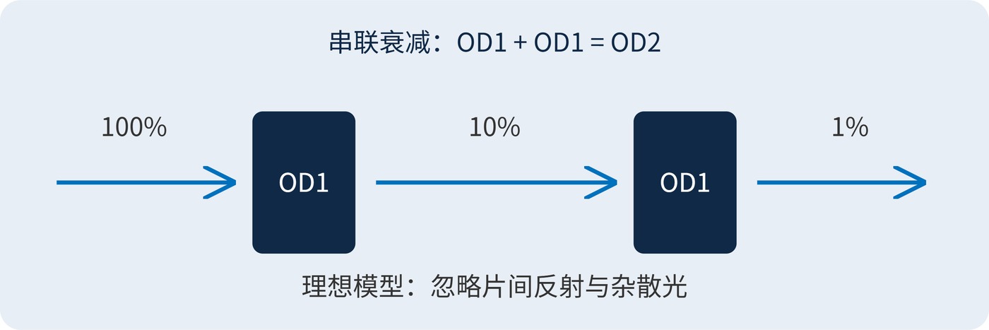
OD1 transmits approximately 10%; it does not subtract a fixed amount of power. Visible neutrality does not establish ultraviolet or near-infrared performance. Out-of-band camera sensitivity can therefore introduce errors. At high OD, light leaking around the filter may exceed the intended transmitted signal.
An ND filter cannot recover saturated data or improve photon-limited signal-to-noise ratio. It is also not automatically a qualified laser safety device. Verify attenuation under the actual spectrum, AOI, polarization and power conditions, with the detector in its linear range, dark signal removed and stray light below the transmission being measured.
 365nm Narrow Bandpass Filter | Ø50mm | T>90%
OT-HBP3659050
365nm Narrow Bandpass Filter; FWHM 10nm; transmission >90%; blocking OD5; size Ø50mm; AOI 0°.
 450nm Narrow Bandpass Filter | Ø50mm
OT-HBP4509050
450nm Narrow Bandpass Filter; FWHM 10nm; transmission >90%; blocking OD5; size Ø50mm; AOI 0°.
 525nm Narrow Bandpass Filter | Ø50mm
OT-HBP5259050
525nm Narrow Bandpass Filter; FWHM 10nm; transmission >90%; blocking OD5; size Ø50mm; AOI 0°.
Send us your drawing and spectral targets — an engineer replies with a feasibility check and quotation within one business day.