Original content by the OOTEE Optics editorial team, drawn from first-hand production line and inspection data. Please credit the source when republishing.
Given limits in expertise and test conditions, the theories, parameters and conclusions here carry no guarantee of absolute accuracy. For technical learning and exchange only - never the sole basis for design, acceptance or selection. Corrections welcome.
A notch filter rejects a narrow wavelength interval around the excitation laser while transmitting light on both sides. In a Raman instrument, strong elastic Rayleigh scattering accompanies much weaker inelastic scattering. Suppressing the laser line helps prevent detector saturation and stray light inside the spectrometer.
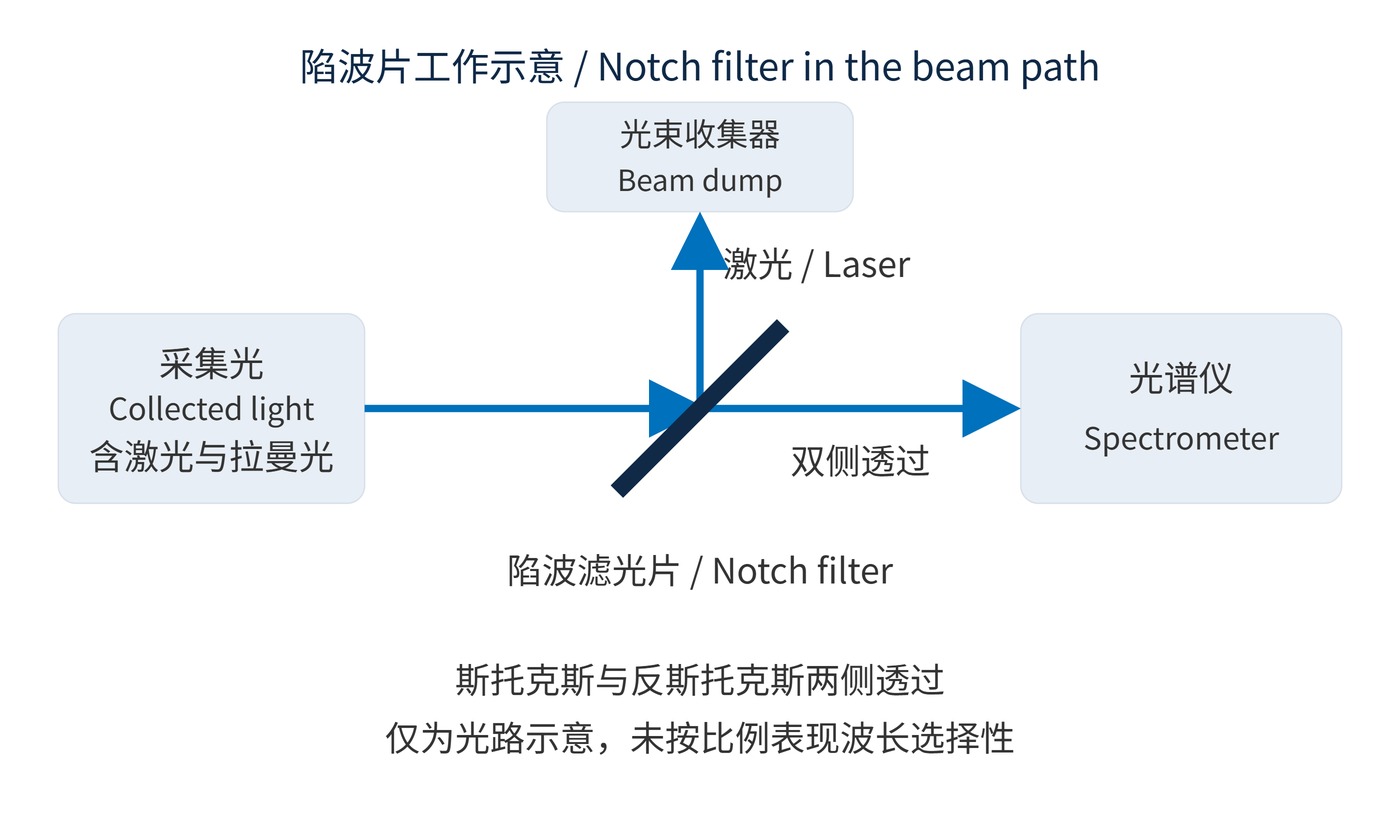
Stokes light lies at longer wavelengths; anti-Stokes light lies at shorter wavelengths. Figure 1 shows how both can reach the spectrometer through a notch filter. This makes it standard tooling for two-sided measurements. Instruments collecting only Stokes light often use a longpass edge filter instead.
Multilayer dielectric filters reject light through interference-enhanced reflection. Volume Bragg gratings provide another approach. Rejected energy is generally redirected rather than entirely absorbed. The center wavelength (CWL) must match the laser. For a notch, full width at half maximum (FWHM) needs an explicit half-depth definition relative to the passband, rather than a transmission-peak definition.
Optical density (OD) describes attenuation at a specified wavelength. Here, transmittance $T$ is a dimensionless power ratio: OD6 means 0.0001% transmission, with no automatic guarantee across the whole rejection band.
$$\mathrm{OD}(\lambda)=-\log_{10}T(\lambda)$$
Convert the required Raman shift into wavelength before choosing the filter. With laser wavelength $\lambda_0$ and scattered wavelength $\lambda$ entered in nm, the equation returns Raman shift in cm⁻¹. Stokes shifts are positive and anti-Stokes shifts negative.
$$\Delta\tilde{\nu}=10^{7}\left(\frac{1}{\lambda_0}-\frac{1}{\lambda}\right)$$
At 532 nm excitation, ±100 cm⁻¹ corresponds to approximately 534.85 nm and 529.18 nm. These wavelengths are only about 2.8 nm from the laser. A center specification of OD6 alone says little about their transmission.
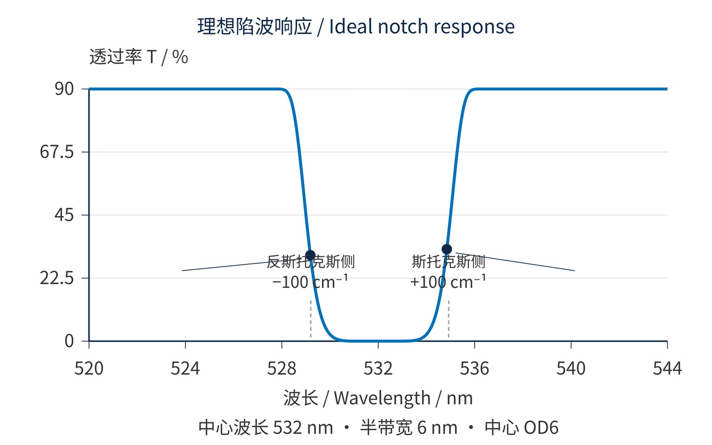
Figure 2 uses an analytical response, evaluated point by point. Define $x=2(\lambda-\lambda_0)/w$, with $\lambda_0=532\,\mathrm{nm}$ and $w=6\,\mathrm{nm}$. The passband transmission is 90%. This is an illustrative response, not a coating simulation or measured product curve.
$$T(\lambda)=0.9-(0.9-10^{-6})\exp[-(\ln 2)x^{8}]$$
Transmission is OD6 at the center and approximately 45% at 529 nm and 535 nm. At the two ±100 cm⁻¹ targets, it is only about 31% and 33%. A half-depth boundary therefore does not establish usable low-shift performance.
Start with measured laser wavelength, linewidth, drift and the smallest required Raman shift. Specify one-sided or two-sided collection. Angle of incidence (AOI), cone angle, polarization and temperature also belong in the specification: angular shifts and polarization splitting can compromise rejection and nearby peaks.
| Item | Example engineering requirement |
|---|---|
| Laser rejection | 532 nm excitation; OD≥6 over 531.8–532.2 nm |
| Signal transmission | ≥80% at both 529.18 nm and 534.85 nm |
| Operating conditions | AOI 0°; cone half-angle≤1°; unpolarized; 23±2 °C |
| Test report | Fine rejection/edge scans, resolution, noise floor and clear aperture |
These are requirements to verify, not promised product capabilities. The 6 nm model fails the signal-transmission requirement. Request both high-dynamic-range rejection data and passband measurements. A measurement limited to OD4 cannot substantiate OD6.
Two-sided spectra support vibrational studies and anti-Stokes thermometry. Temperature estimates require calibration of the wavelength response of the filter, grating and detector. Lattice vibrations, interlayer modes and phase transitions can require exceptionally narrow rejection and careful control of instrument stray light.
For routine molecular fingerprints, balance laser rejection against throughput over the useful spectrum. Place the filter in a collimated collection section and route reflected light to a beam dump to limit feedback and secondary scattering.
Accept the system using residual laser leakage, transmission at the smallest target shift and detector dynamic range together, under the actual illumination conditions.
Optical layouts and noise budgets for time-resolved Raman rejection are surveyed in a review of time-resolved Raman detection freely available on PubMed Central.
 365nm Narrow Bandpass Filter | Ø50mm | T>90%
OT-HBP3659050
365nm Narrow Bandpass Filter; FWHM 10nm; transmission >90%; blocking OD5; size Ø50mm; AOI 0°.
 450nm Narrow Bandpass Filter | Ø50mm
OT-HBP4509050
450nm Narrow Bandpass Filter; FWHM 10nm; transmission >90%; blocking OD5; size Ø50mm; AOI 0°.
 525nm Narrow Bandpass Filter | Ø50mm
OT-HBP5259050
525nm Narrow Bandpass Filter; FWHM 10nm; transmission >90%; blocking OD5; size Ø50mm; AOI 0°.
Send us your drawing and spectral targets — an engineer replies with a feasibility check and quotation within one business day.