Original content by the OOTEE Optics editorial team, drawn from first-hand production line and inspection data. Please credit the source when republishing.
Given limits in expertise and test conditions, the theories, parameters and conclusions here carry no guarantee of absolute accuracy. For technical learning and exchange only - never the sole basis for design, acceptance or selection. Corrections welcome.
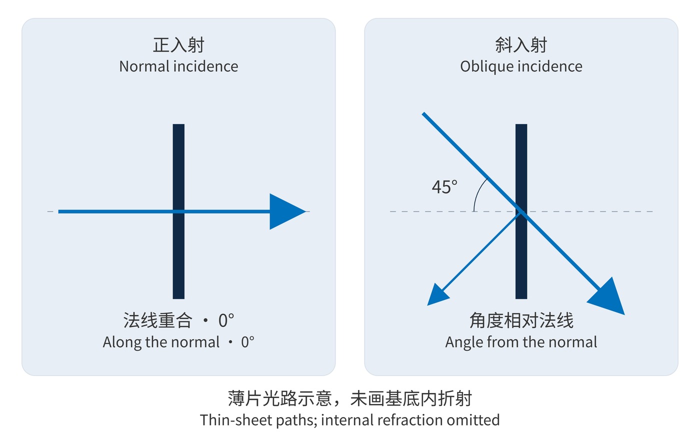
Normal and oblique incidence define different operating conditions for an interference filter. Angle of incidence (AOI) is measured from the surface normal: normal incidence is 0°. As Fig. 1 shows, a 45° arrangement separates a reflected beam from the transmitted path, but also introduces different spectral, polarization and mounting requirements.
Center wavelength (CWL), full width at half maximum (FWHM) and optical density (OD) are incomplete specifications without this geometry. A filter accepted at 0° is not automatically qualified for 45°. The engineering task is to turn the system layout into requirements that can be manufactured and verified.
The phase thickness of a coating layer includes the cosine of its internal propagation angle. For incidence from air, an effective-index approximation predicts the position of a spectral feature:
$$\lambda(\theta)\approx\lambda_0\sqrt{1-\frac{\sin^2\theta}{n_{\mathrm{eff}}^2}}$$
Here, $\theta$ is the external AOI. The effective index depends on the coating, wavelength and polarization; it is not the substrate index. With $\lambda_0=780\,\mathrm{nm}$ and $n_{\mathrm{eff}}=2.0$, the estimated centers are 773.4 nm at 15° and 729.6 nm at 45°. These are screening estimates, not a coating qualification.
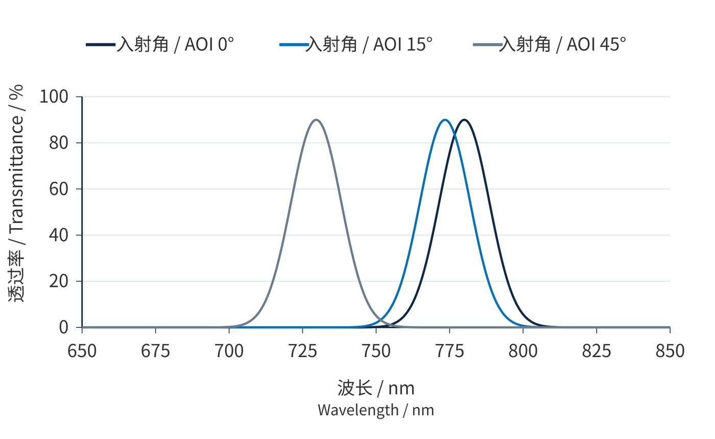
Fig. 2 uses these centers in a Gaussian passband sampled every 0.5 nm. Peak transmission stays at 90% and FWHM at 20 nm; only AOI changes. This illustrative model excludes polarization splitting, bandwidth changes and actual blocking leakage. It cannot establish an OD rating. Real oblique designs require separate evaluation of S polarization, perpendicular to the incidence plane, and P polarization, parallel to it.
A chief-ray angle also leaves out the cone of a converging beam and the variation across an imaging field. The detector integrates an energy-weighted response. Research on tilted filters in converging beams shows that angular variation across the pupil can affect the imaging response as well.
Geometry also sets the required clear aperture. A collimated circular beam of diameter $D$ produces an elliptical footprint with major axis:
$$L=\frac{D}{\cos\theta}$$
A 10 mm beam therefore occupies about 14.1 mm at 45°, before decenter and edge margins. A parallel plate generally leaves the emerging ray parallel to the incident ray but laterally displaced. Fig. 1 uses a thin-sheet representation and omits internal refraction.
Choose the filter location first. For narrow-line transmission, evaluate a near-normal arrangement in collimated space. Where transmitted and reflected channels must separate, design for the actual working angle. Tilting a 0° filter alone does not guarantee performance at 45°.
| Item | Illustrative requirement, not a product rating | Acceptance focus |
|---|---|---|
| Geometry | AOI 45° ±0.5°; cone half-angle ≤2° | Separate mount tolerance from beam spread |
| Passband | CWL 780 nm; FWHM 20 nm; peak ≥90% at operating AOI | Specify individual S/P limits or explicit weights |
| Blocking | OD6 over 400–700 nm | Verify angular and polarization boundaries |
| Beam size | 10 mm diameter | Allow for footprint, field and decenter |
OD6 means transmission no greater than 0.0001%. State the wavelength interval and measurement capability together. The example requirements need coating feasibility checks and may involve trade-offs. When comparing narrow bandpass filters, establish whether quoted values apply at 0° or at the intended operating angle before comparing CWL tolerances.
An angular error should consume part of the wavelength budget. Around 45°, the same approximation gives about 1.82 nm per degree: a ±0.5° mounting error contributes approximately ±0.91 nm. Manufacturing variation and temperature drift need allocations within the same overall budget.
In narrowband machine vision, a more nearly collimated filter location can reduce spectral differences across the image. Wide-field designs need ray tracing of both chief and aperture rays at the field edge. Stopping down reduces cone angle, but also sacrifices collected light.
Fluorescence and multichannel instruments often use 45° dichroic mirrors. Specify transmission in one channel and reflection in the other, including S/P edge positions and mechanical clearance for the reflected beam. Even a small tilt used to divert back-reflections needs a check that the signal remains inside the guaranteed passband.
The optical drawing, mechanical datum and acceptance report should share one angle convention. Qualification rests on the worst permitted combination of angle, cone and polarization for both passband and blocking performance.
 365nm Narrow Bandpass Filter | Ø50mm | T>90%
OT-HBP3659050
365nm Narrow Bandpass Filter; FWHM 10nm; transmission >90%; blocking OD5; size Ø50mm; AOI 0°.
 450nm Narrow Bandpass Filter | Ø50mm
OT-HBP4509050
450nm Narrow Bandpass Filter; FWHM 10nm; transmission >90%; blocking OD5; size Ø50mm; AOI 0°.
 525nm Narrow Bandpass Filter | Ø50mm
OT-HBP5259050
525nm Narrow Bandpass Filter; FWHM 10nm; transmission >90%; blocking OD5; size Ø50mm; AOI 0°.
Send us your drawing and spectral targets — an engineer replies with a feasibility check and quotation within one business day.



