Original content by the OOTEE Optics editorial team, drawn from first-hand production line and inspection data. Please credit the source when republishing.
Given limits in expertise and test conditions, the theories, parameters and conclusions here carry no guarantee of absolute accuracy. For technical learning and exchange only - never the sole basis for design, acceptance or selection. Corrections welcome.
Optical density (OD) specifies attenuation within a defined blocking band. OD3, OD4 and OD6 correspond to transmittances of 0.1%, 0.01% and 0.0001%. These numbers describe wavelength-dependent filter performance; they do not assign a signal-to-noise grade to an instrument.
The useful question is how much unwanted light reaches the filter, and how much can remain at the detector. OD4 may be ample for a bright inspection target yet inadequate for weak fluorescence. Choose a depth from a leakage budget rather than an application label.
For power transmittance $T$, expressed as a fraction:
$$\mathrm{OD}(\lambda)=-\log_{10}T(\lambda)$$
Blocking can involve reflection or absorption; OD alone does not distinguish them. The Florida State University microscopy tutorial explains this distinction. All numerical scenarios below are design calculations, not measured product specifications.
Let $B_0$ be the unwanted-light electron count that would reach the detector without blocking, and $S$ the useful electron count after passband losses. If leakage must stay below a fraction $\alpha$ of the signal, narrowband interference gives:
$$B=B_0\,10^{-\mathrm{OD}},\qquad \mathrm{OD}_{\mathrm{req}}\geq\log_{10}\frac{B_0}{\alpha S}$$
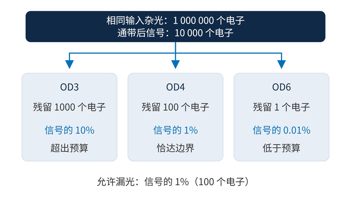
This assumes linear detection and no bypass path. Fig. 1 holds $B_0=10^6$ electrons and $S=10^4$ electrons constant. OD3 leaves 1000 electrons, OD4 leaves 100, and OD6 leaves 1. With a 1% leakage allowance, OD4 sits exactly on the limit, leaving no margin for source variation or operating-angle changes.
For broadband background, integrate the source spectrum, filter transmittance and detector response. A single-wavelength OD cannot represent the entire background. Leakage also adds shot noise and consumes full-well capacity. Subtracting its mean cannot remove that noise or restore information lost to saturation.
A leakage allowance is therefore only one acceptance criterion. A channel can satisfy its mean-background limit and still miss its precision target if photon statistics are poor. Conversely, lowering background well below other noise sources may offer little benefit. Check the actual exposure and detector gain when deciding whether additional blocking will improve the measurement.
For example, a CWL 780 nm, FWHM 20 nm bandpass specification could separately define minimum blocking over 400–740 nm and 820–1100 nm. Transitions within 740–820 nm need their own requirements. This illustrative specification says nothing about adequate rejection of a 760 nm laser.
For an instrument check, record a background frame with illumination on and the target signal absent. Compare it with the net signal from the target. Remove dark-current and readout offsets first. The remaining background may include in-band light, so this checks the total background allowance rather than measuring filter OD directly. If it fails, isolate source tails, housing reflections and gaps around the filter before requesting a deeper coating.
Make margin traceable to an operating condition. A tenfold increase in unwanted light requires another 1 OD when signal is unchanged. If signal also halves, the required depth rises by a further 0.30 OD. A blanket instruction to buy the next grade can therefore be misleading. Document the maximum source output, minimum useful signal and exposure setting used for acceptance, so the result can be repeated after component or illumination changes.
The table assumes a 1% leakage allowance and interference confined to guaranteed blocking bands. The ratio includes detector response and passband losses. These are theoretical limits before adding margin.
| Candidate depth | Budget condition | Possible use |
|---|---|---|
| OD3 | $B_0/S\leq10$ | Bright-target machine vision under enclosed illumination, rejecting out-of-band ambient light |
| OD4 | $B_0/S\leq100$ | Shielded LED-excited detection after geometry has reduced excitation pickup |
| OD6 | $B_0/S\leq10^4$ | Weak fluorescence or channels requiring strong rejection of out-of-band scattered laser light |
If $B_0/S=10^5$, the same budget requires at least OD7. OD6 is insufficient. Reduce excitation scattering, improve baffling or evaluate complementary blocking filters. Shorter exposure generally reduces both signal and leakage, leaving their ratio unchanged.
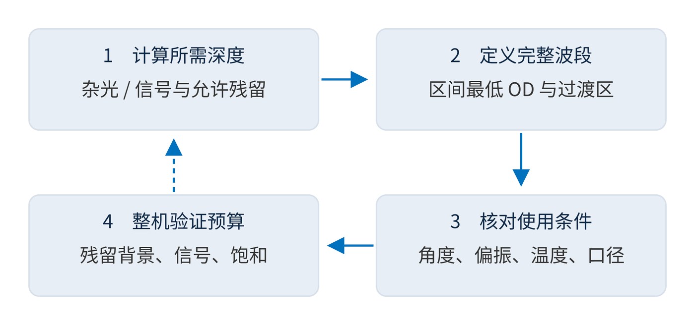
Confirm residual background, retained signal and detector linearity under worst-case conditions. Together, those checks determine whether OD3, OD4 or OD6 is sufficient.
 365nm Narrow Bandpass Filter | Ø50mm | T>90%
OT-HBP3659050
365nm Narrow Bandpass Filter; FWHM 10nm; transmission >90%; blocking OD5; size Ø50mm; AOI 0°.
 450nm Narrow Bandpass Filter | Ø50mm
OT-HBP4509050
450nm Narrow Bandpass Filter; FWHM 10nm; transmission >90%; blocking OD5; size Ø50mm; AOI 0°.
 525nm Narrow Bandpass Filter | Ø50mm
OT-HBP5259050
525nm Narrow Bandpass Filter; FWHM 10nm; transmission >90%; blocking OD5; size Ø50mm; AOI 0°.
Send us your drawing and spectral targets — an engineer replies with a feasibility check and quotation within one business day.



