Original content by the OOTEE Optics editorial team, drawn from first-hand production line and inspection data. Please credit the source when republishing.
Given limits in expertise and test conditions, the theories, parameters and conclusions here carry no guarantee of absolute accuracy. For technical learning and exchange only - never the sole basis for design, acceptance or selection. Corrections welcome.
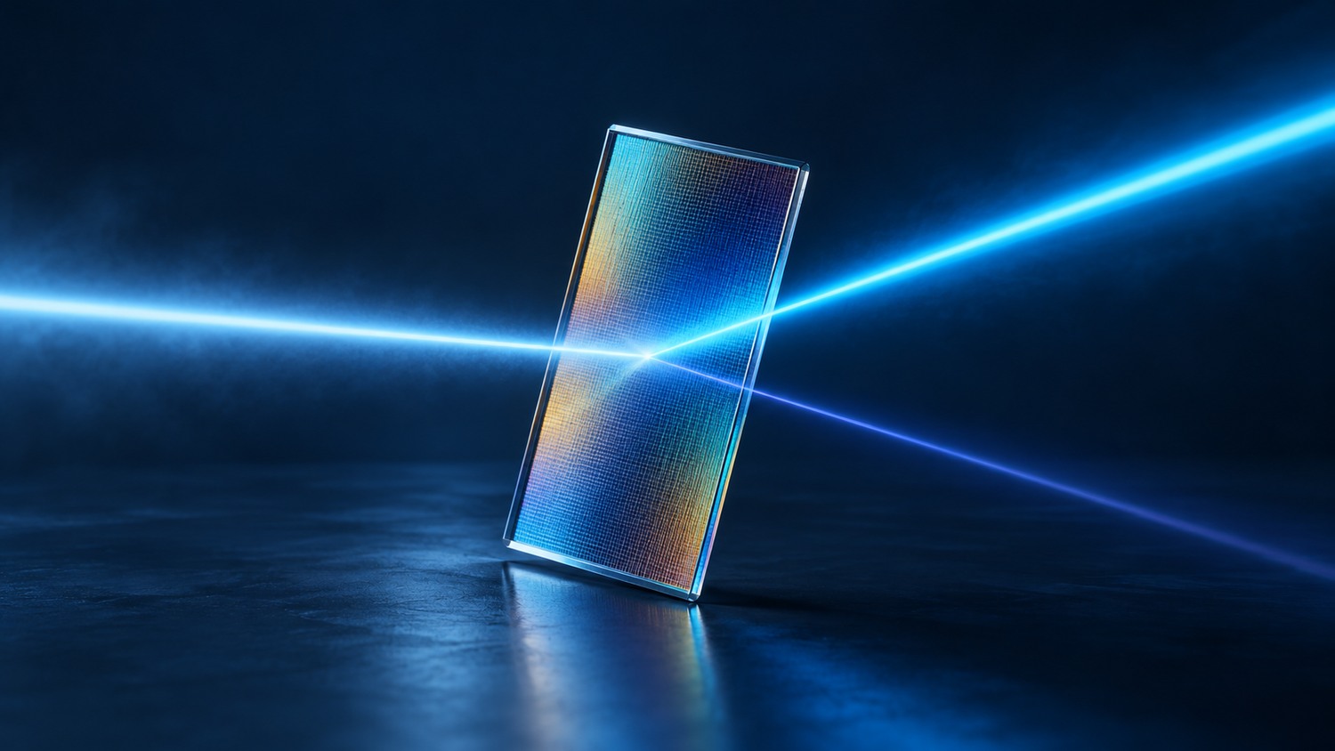
A filter has a polarization-dependent response when its transmission, reflection or phase response differs for orthogonal electric-field orientations. The practical question is simple: why can rotating a laser's polarization change detector power even when the filter mount stays still?
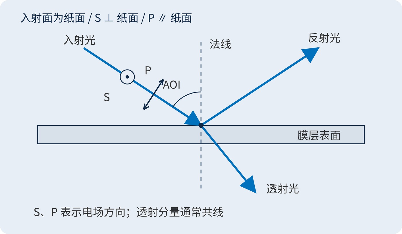
The angle of incidence (AOI) is measured from the surface normal. The incident ray and that normal define the plane of incidence. S polarization has its electric field perpendicular to this plane; P polarization lies within it. Fig. 1 shows this geometry. These directions belong to the beam geometry, rather than permanent vertical and horizontal axes on the optic. For ideal isotropic coatings, the two responses coincide at normal incidence.
Tilting a multilayer changes propagation phase and the coupling at each interface. For isotropic, nonmagnetic layers, a normalized optical-admittance convention gives:
$$q_{s,j}=n_j\cos\theta_j,\qquad q_{p,j}=\frac{n_j}{\cos\theta_j}$$
Here, $n_j$ is the refractive index of layer $j$, and $\theta_j$ is its internal propagation angle, not the external AOI. The different admittances help explain why S and P spectra can develop different peak transmission, edges, bandwidth and leakage. Matching center wavelength (CWL) and full width at half maximum (FWHM) does not ensure matching spectra. The direction and magnitude of a particular edge separation depend on the coating design.
If the detector does not analyze polarization and the orthogonal powers add, transmission at a fixed wavelength is:
$$T_{\mathrm{eff}}=f_sT_s+(1-f_s)T_p$$
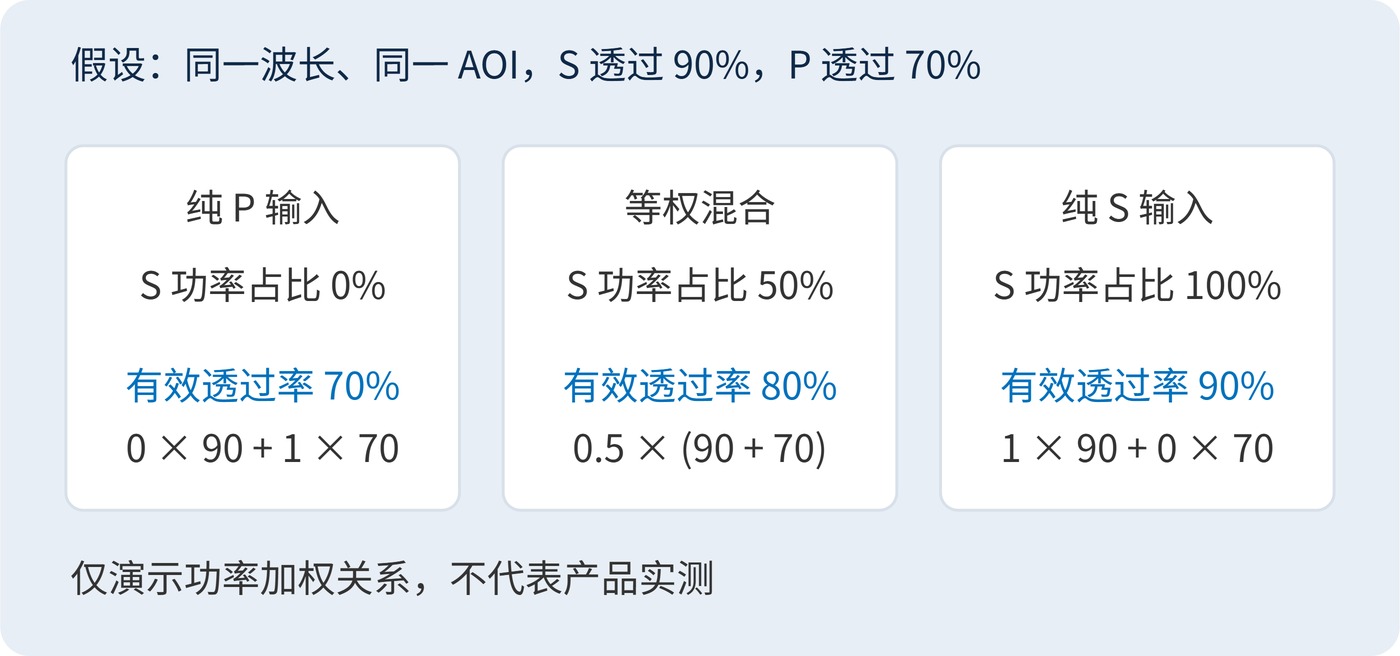
The weight $f_s$ is the incident S power fraction. In Fig. 2, assumed values of 90% for S and 70% for P give 80% for an equal mixture, but 70% for pure P. These are arithmetic examples, not measured product data. A downstream analyzer can make relative phase relevant; a power-weighted average alone then cannot describe the complete optical train.
Optical density (OD) must be derived from the linear power ratio, with transmission expressed between 0 and 1:
$$\mathrm{OD}_{\mathrm{eff}}=-\log_{10}\!\left[f_s10^{-\mathrm{OD}_s}+(1-f_s)10^{-\mathrm{OD}_p}\right]$$
Equal incident powers with OD6 for S and OD4 for P produce approximately OD4.30 overall. Averaging the OD values to obtain OD5 would substantially understate leakage.
Establish the polarization state at the filter location and the actual angular distribution. A converging beam contains oblique rays even when its chief ray is normal to the filter. Scanning can also rotate the incidence plane. A single on-axis measurement cannot cover these conditions.
| Item | Example requirement |
|---|---|
| Nominal target | CWL 780 nm, FWHM 20 nm; identify the reference polarization |
| Beam and angles | Collimated beam, AOI 10° ± 2°; S and P spectra at 8°, 10° and 12° |
| Signal acceptance | Minimum transmission ≥85% across 775–785 nm for each polarization |
| Blocking acceptance | OD6 across 400–700 nm for both polarizations; declare measurement dynamic range |
This illustrates a specification format; feasibility requires a coating-design review. For unknown or rotating polarization, accept against the worse response. For a stable polarized source, document the mounting orientation and constrain rotation. An unpolarized average spectrum cannot establish worst-case performance.
Keep each acceptance limit tied to its measurement conditions. A supplier's nominal bandwidth describes only part of the requirement: the useful signal must remain inside the accepted wavelength interval at every specified angle. Likewise, a deep blocking result for S cannot compensate for excessive P leakage. Record the polarization orientation with the test setup so that a later incoming inspection can reproduce the same optical geometry.
In laser machine vision, a target can alter the return polarization, and the filter can convert that change into image contrast. In fluorescence detection, an oblique spectral splitter may weight excitation leakage and emission differently, affecting channel ratios. Scanning receivers need checks at field edges, where angle and polarization can change together.
For troubleshooting, hold source power and detector settings constant, measure S and P separately with an input polarizer, and compare the operating angles at the same wavelength. Investigating phase effects requires suitable polarization analysis. A power measurement without an analyzer does not determine the complete polarization state.
Evaluate useful signal and blocking under the same wavelength, angle and polarization conditions, then allocate system margin against the worst case.
Technical references: Fresnel equations and interface response; Angular and polarization effects in interference filters.
 365nm Narrow Bandpass Filter | Ø50mm | T>90%
OT-HBP3659050
365nm Narrow Bandpass Filter; FWHM 10nm; transmission >90%; blocking OD5; size Ø50mm; AOI 0°.
 450nm Narrow Bandpass Filter | Ø50mm
OT-HBP4509050
450nm Narrow Bandpass Filter; FWHM 10nm; transmission >90%; blocking OD5; size Ø50mm; AOI 0°.
 525nm Narrow Bandpass Filter | Ø50mm
OT-HBP5259050
525nm Narrow Bandpass Filter; FWHM 10nm; transmission >90%; blocking OD5; size Ø50mm; AOI 0°.
Send us your drawing and spectral targets — an engineer replies with a feasibility check and quotation within one business day.



