Original content by the OOTEE Optics editorial team, drawn from first-hand production line and inspection data. Please credit the source when republishing.
Given limits in expertise and test conditions, the theories, parameters and conclusions here carry no guarantee of absolute accuracy. For technical learning and exchange only - never the sole basis for design, acceptance or selection. Corrections welcome.
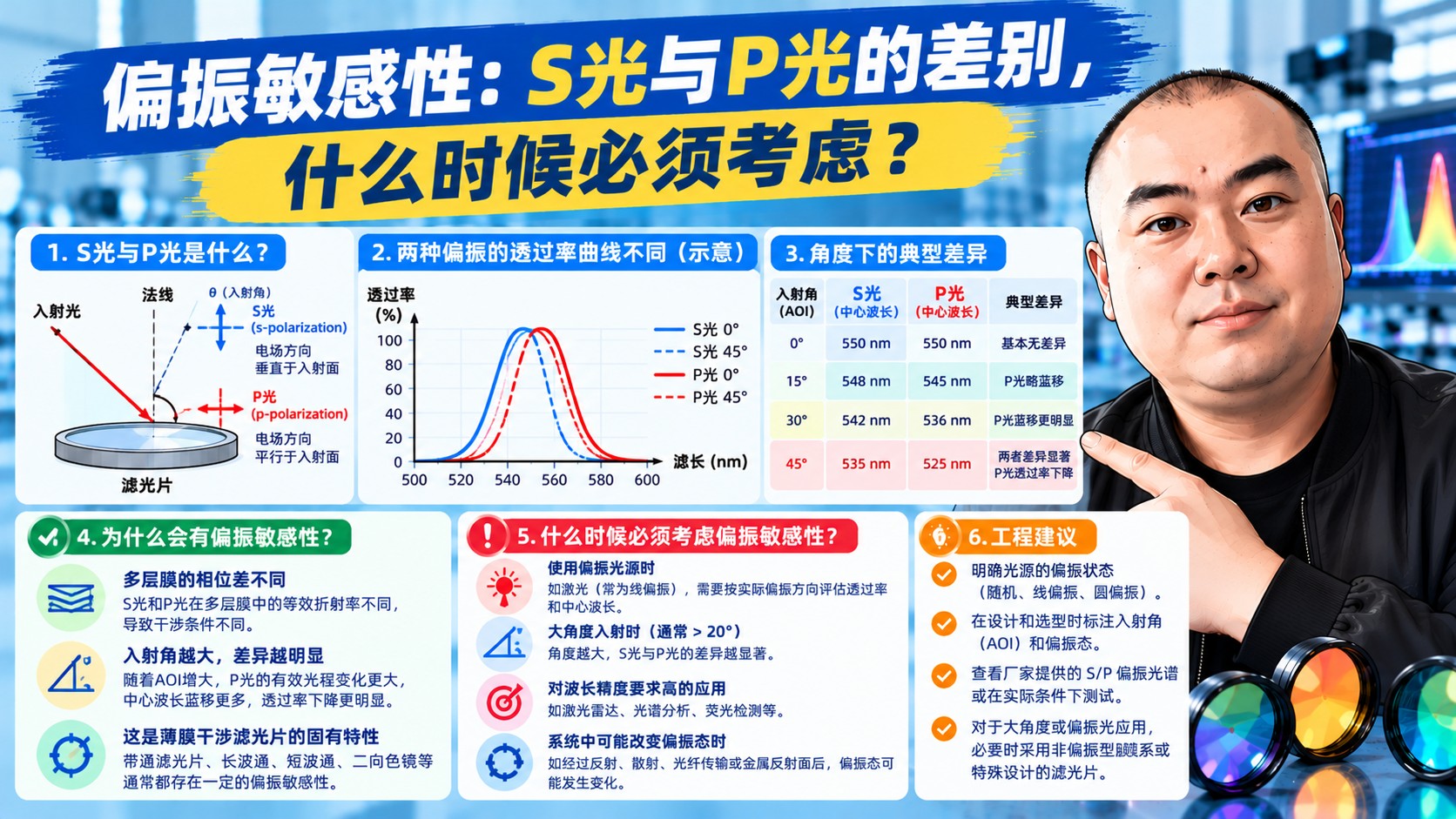
Polarization sensitivity is the difference in behavior between S- and P-polarized light on the same filter - in transmission level, center wavelength or edge position.
S polarization has its electric field perpendicular to the plane of incidence, P polarization parallel. The two already behave differently at any thin-film interface (think Brewster's angle), so a coating stack responds differently to them as well.
| Condition | S versus P difference | Attention needed? |
|---|---|---|
| AOI 0 degrees | Essentially none | Usually ignore |
| AOI 10-20 degrees | A few nanometers | Watch it for narrowband work |
| AOI 45 degrees | Tens of nanometers | Must evaluate separately |
| Lasers (linearly polarized) | Depends on orientation | State the polarization explicitly |
The classic case is dichroic mirrors and beam splitters: they work at 45 degrees by design, and their S and P edges commonly sit 20-40 nm apart. A curve measured with unpolarized light is the average of the two and looks deceptively soft. Design against that averaged curve and the installed part will either reflect too little or transmit too little.
The reflection coefficient of every layer depends on polarization. P light sees a different effective index at each interface than S light - effectively a different optical thickness - so the interference condition shifts. The larger the angle, the larger the separation; near Brewster's angle the P reflection can even approach zero.
The same physics is what makes a polarizing beam splitter work: it deliberately maximizes the S/P difference so P transmits and S reflects.
"AOI 45 degrees; both Ts and Tp at least 90% from 520 to 560 nm and no more than 0.1% (OD3) from 450 to 500 nm."
Requiring S and P separately rather than one averaged curve is the single most effective step against disputes later on.
Want the polarization impact assessed? Send the working angle, source polarization state and wavelength requirements to sales@ootee.cn for simulated S and P curves.
 365nm Narrow Bandpass Filter | Ø50mm | T>90%
OT-HBP3659050
365nm Narrow Bandpass Filter; FWHM 10nm; transmission >90%; blocking OD5; size Ø50mm; AOI 0°.
 450nm Narrow Bandpass Filter | Ø50mm
OT-HBP4509050
450nm Narrow Bandpass Filter; FWHM 10nm; transmission >90%; blocking OD5; size Ø50mm; AOI 0°.
 525nm Narrow Bandpass Filter | Ø50mm
OT-HBP5259050
525nm Narrow Bandpass Filter; FWHM 10nm; transmission >90%; blocking OD5; size Ø50mm; AOI 0°.
Send us your drawing and spectral targets — an engineer replies with a feasibility check and quotation within one business day.



