Original content by the OOTEE Optics editorial team, drawn from first-hand production line and inspection data. Please credit the source when republishing.
Given limits in expertise and test conditions, the theories, parameters and conclusions here carry no guarantee of absolute accuracy. For technical learning and exchange only - never the sole basis for design, acceptance or selection. Corrections welcome.
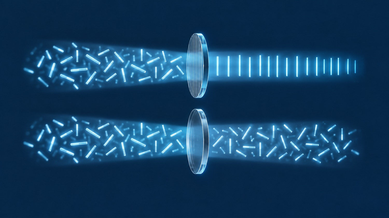
A polarizing filter selects an electric-field orientation. A non-polarizing filter aims to give orthogonal polarization components similar intensity responses. These are different functions from depolarization, even when purchasing descriptions use the terms interchangeably.
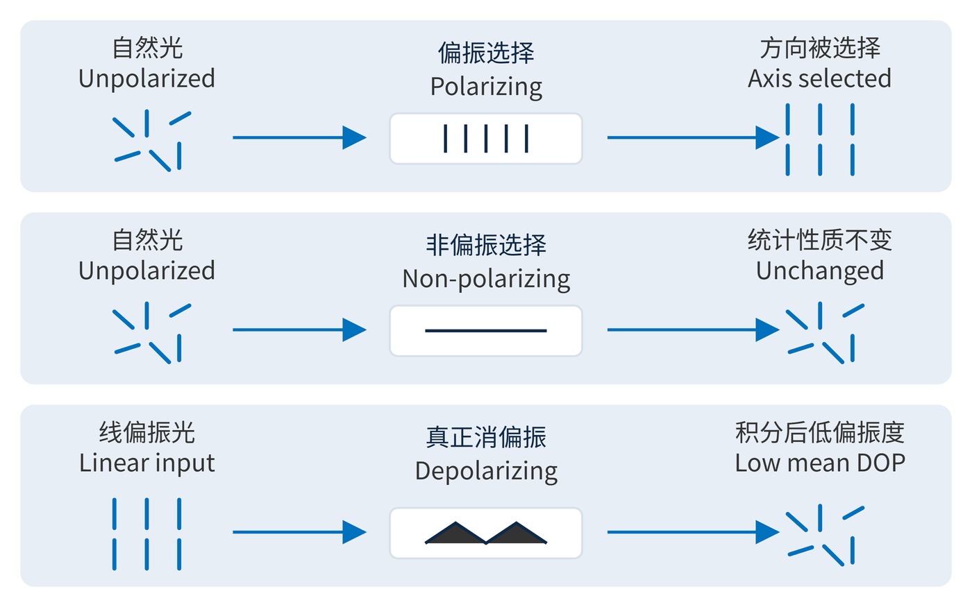
As Fig. 1 shows, a linear polarizer selects one direction from unpolarized illumination. An ideal polarization-independent element leaves its polarization statistics unchanged; it also does not scramble an incoming linearly polarized beam. A depolarizer instead introduces spatial, spectral or temporal variations that reduce the degree of polarization measured over the receiver's averaging window.
Polarizers exploit anisotropic absorption, reflection or birefringent beam separation. For an ideal linear polarizer illuminated by a linearly polarized beam at a fixed wavelength, Malus' law relates transmitted intensity to the angle between the input orientation and transmission axis:
$$I(\theta)=I_0\cos^2\theta$$
Here $I_0$ is the incident intensity. Real devices have finite parallel-axis and crossed-axis transmittances. This article defines extinction ratio using the same incident power for both measurements:
$$\mathrm{ER}=\frac{T_{\parallel}}{T_{\perp}}$$
For example, 90% and 0.09% at 550 nm and normal incidence give 1000:1. Unpolarized single-pass transmission is their average, approximately 45.045%, rather than 90%. These are calculation examples, not product specifications.
For non-polarizing optics, specify the difference between $T_s$ and $T_p$, and between $R_s$ and $R_p$ when reflection matters. Equal intensities do not guarantee an unchanged polarization ellipse: differential phase also matters. Depolarizers require a different quantity, the degree of polarization (DOP), calculated from the Stokes parameters:
$$\mathrm{DOP}=\frac{\sqrt{S_1^2+S_2^2+S_3^2}}{S_0}$$
DOP ranges from 0 to 1. Report it with source bandwidth, collection aperture and integration time. Rotating a linear analyzer alone cannot distinguish circular polarization from unpolarized light; full polarimetry is required.
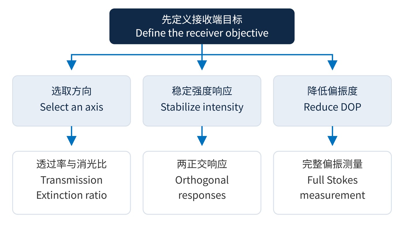
Start with the incident polarization and the receiver's error budget. Fig. 2 separates three acceptance routes. The following numbers illustrate independent specification examples and require confirmation against the system design.
| Required function | Example specification | Acceptance method |
|---|---|---|
| Select linear polarization | 550 nm; angle of incidence (AOI) 0°; parallel transmission ≥85%; extinction ratio ≥1000:1 | Verify axis marking, angular response and dark-signal subtraction. |
| Limit polarization bias during wavelength selection | Center wavelength (CWL) 780 nm; full width at half maximum (FWHM) 20 nm; both polarization transmittances ≥90% across 770–790 nm; difference ≤2 percentage points; AOI 0°±2° | Measure both orthogonal inputs, including passband edges. |
| Reduce measured polarization | Specified 500–700 nm source; output DOP ≤0.05; collection aperture 5 mm; integration time 10 ms | Record input state, spectral distribution and receiver sampling. |
Specify spectral blocking separately through optical density (OD) and its wavelength interval, for example OD≥4 across 400–700 nm. This does not imply a 10000:1 polarization extinction ratio. Include clear aperture, power density and temperature limits. FWHM describes spectral width, not polarization discrimination.
Agree on the reference plane and measurement uncertainty before comparing data. A two-percentage-point transmission difference is an absolute difference, not a relative percentage. Measure both inputs with the same incident-power normalization, aperture and angular distribution. Otherwise source drift or collection changes can look like polarization dependence.
Crossed illumination and camera polarizers can suppress specular glare in machine vision. Surface scattering, stress birefringence and metallic reflection affect the result, so test representative parts. Polarization analysis and stress inspection deliberately exploit directional selection and therefore need controlled axis alignment.
For spectroscopy with a changing input polarization, low-dependence filters and beam splitters are a useful starting point. If a downstream grating remains sensitive, evaluate a depolarizer under the actual spectral and spatial collection conditions. Performance obtained with broadband illumination cannot simply be assigned to a narrow-linewidth laser.
Keep input state, wavelength range, angle and receiver conditions with every acceptance record. Stable intensity, polarization preservation and low DOP are separate objectives and need separate evidence.
For a depolarizer, repeat the measurement after matching the collection aperture and exposure to the intended instrument. A result averaged across the entire beam may conceal structure sampled by an individual detector pixel. Acceptance belongs to the assembled measurement conditions as well as to the optical element.
Published treatments of Malus' law, extinction ratio and Stokes parameters can be found in university microscopy tutorials on polarization and analyzers; the averaging requirements of depolarizers are discussed systematically in the RP Photonics encyclopedia.
 365nm Narrow Bandpass Filter | Ø50mm | T>90%
OT-HBP3659050
365nm Narrow Bandpass Filter; FWHM 10nm; transmission >90%; blocking OD5; size Ø50mm; AOI 0°.
 450nm Narrow Bandpass Filter | Ø50mm
OT-HBP4509050
450nm Narrow Bandpass Filter; FWHM 10nm; transmission >90%; blocking OD5; size Ø50mm; AOI 0°.
 525nm Narrow Bandpass Filter | Ø50mm
OT-HBP5259050
525nm Narrow Bandpass Filter; FWHM 10nm; transmission >90%; blocking OD5; size Ø50mm; AOI 0°.
Send us your drawing and spectral targets — an engineer replies with a feasibility check and quotation within one business day.