Original content by the OOTEE Optics editorial team, drawn from first-hand production line and inspection data. Please credit the source when republishing.
Given limits in expertise and test conditions, the theories, parameters and conclusions here carry no guarantee of absolute accuracy. For technical learning and exchange only - never the sole basis for design, acceptance or selection. Corrections welcome.
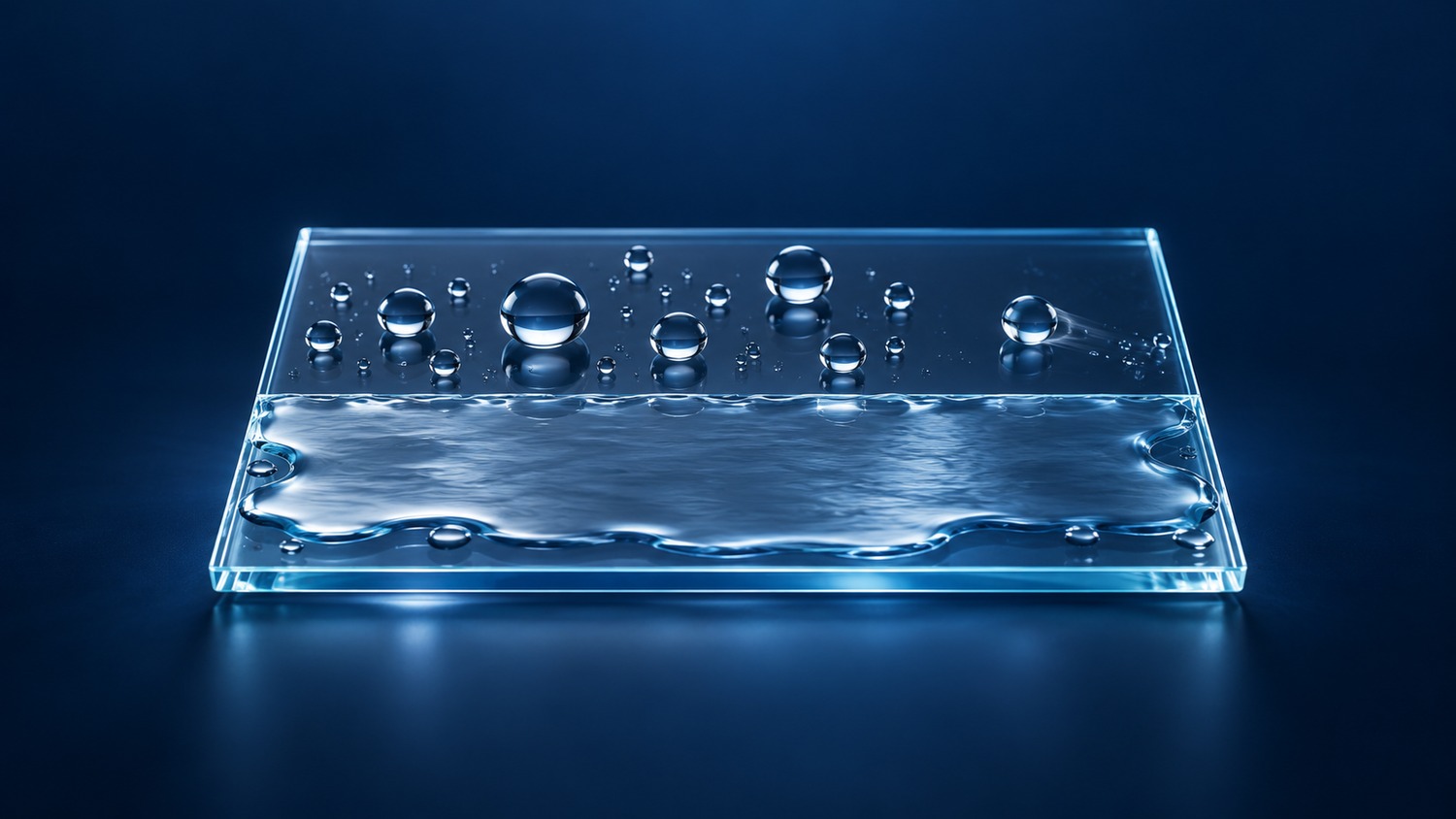
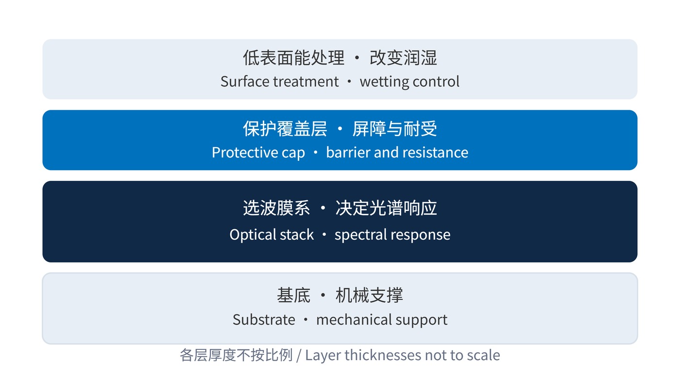
A protective overcoat is an outer layer that helps an optical filter withstand exposure, contamination or cleaning. It is not removable shipping film. A dense inorganic cap and a low surface energy treatment serve different purposes: the cap provides a barrier and a more resistant surface, while the treatment changes how liquids wet that surface.
Fig. 1 separates these functions from the wavelength-selective stack. An oxide such as SiO₂ may be suitable as a cap, but its name alone establishes neither freedom from pinholes nor chemical compatibility. A hydrophobic finish is likewise not a scratchproof hard layer. The useful question is which service-related failure the outer layer reduces.
For an ideal smooth, chemically uniform surface at equilibrium, Young's equation relates contact angle to interfacial tensions. The subscripts denote solid–vapor, solid–liquid and liquid–vapor interfaces:
$$\gamma_{\mathrm{SV}}-\gamma_{\mathrm{SL}}=\gamma_{\mathrm{LV}}\cos\theta$$
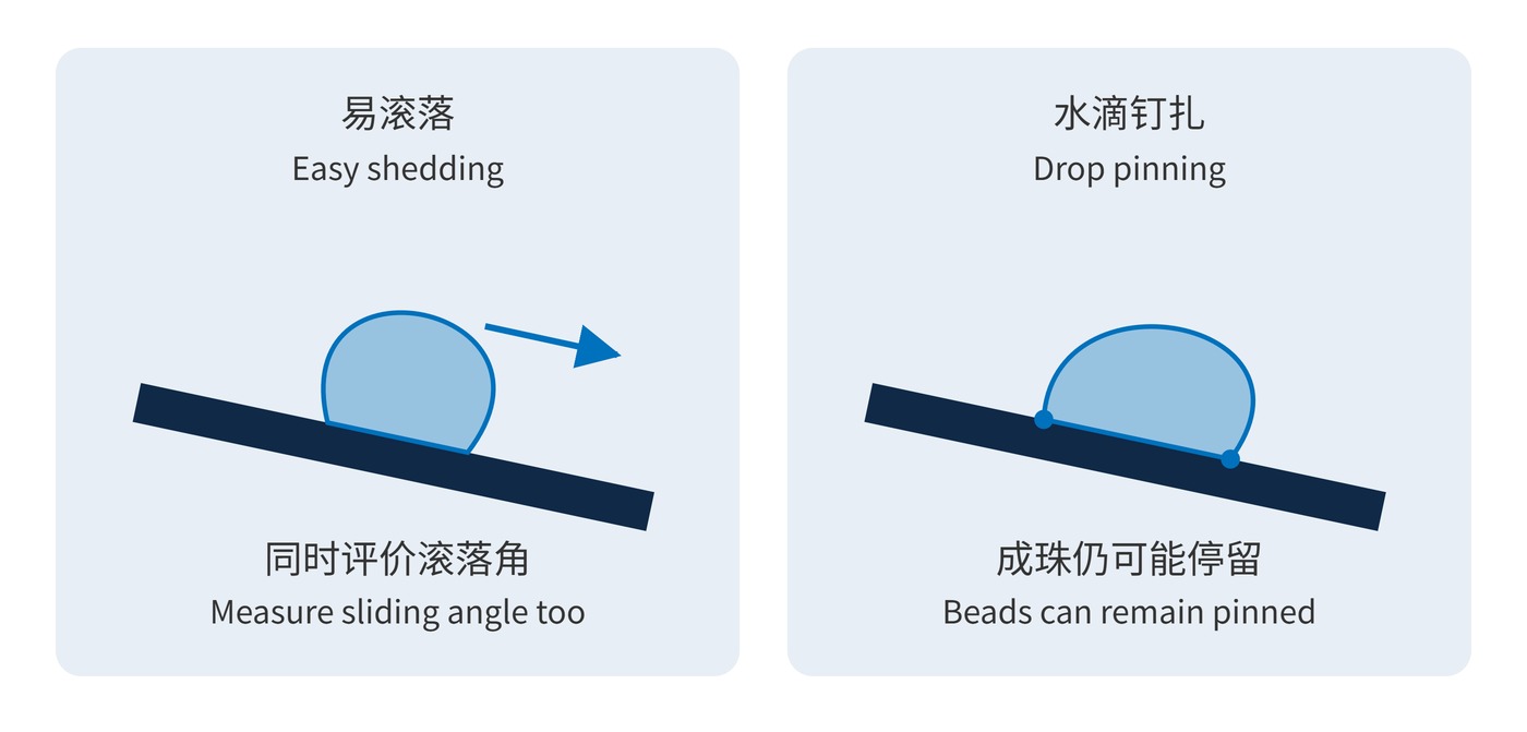
A water contact angle above 90° indicates hydrophobic behavior, but does not guarantee easy shedding. As Fig. 2 illustrates, pinning can hold a rounded drop in place. Contact angle hysteresis—the difference between advancing and receding angles—and the sliding angle at a specified drop volume provide additional information. Wetting and contact-angle teaching material published by the MIT NanoStructures and NanoMechanics Laboratory explains the underlying distinctions.
An overcoat also has an optical cost. For a uniform transparent layer at normal incidence, its single-pass phase thickness is:
$$\delta(\lambda)=\frac{2\pi n(\lambda)d}{\lambda}$$
With $n=1.45$, $d=100\,\mathrm{nm}$ and $\lambda=780\,\mathrm{nm}$, the phase is approximately 1.17 radians. The layer therefore requires joint modeling with the original stack; this number alone predicts no particular wavelength shift.
Record center wavelength (CWL), full width at half maximum (FWHM), optical density (OD) and angle of incidence (AOI) before and after treatment and cleaning. Water contact angle cannot reveal added absorption, scatter or fluorescence background.
Identify the exposed face first. A frequently cleaned external surface has different needs from a filter sealed inside an instrument. A front-face coating does not automatically seal edges, mounting interfaces or adhesive joints.
Describe the liquid and cleaning process rather than requesting a generic “durable coating.” Water repellency does not establish oil repellency, and either property can change with wear. Include the required face and exposure path in the drawing so that a protective treatment is applied where it can affect maintenance.
| Exposure | Check first | Record for acceptance |
|---|---|---|
| Rain or condensation | Wetting and drainage | Drop volume, contact angle, sliding angle |
| Oil and fingerprints | Oil repellency and cleaner compatibility | Specified soil and remaining residue |
| Repeated wiping | Adhesion and treatment retention | Load, cloth, cycles and scatter change |
| Weak-signal or UV detection | Absorption and emission background | In-band transmission and blank signal |
One illustrative qualification could use CWL 780 nm, FWHM 20 nm and AOI 0°, with initial minimum passband transmission of 90% and OD≥6 throughout 400–700 nm. After 100 agreed cleaning cycles, require no more than a 1 percentage point loss in minimum passband transmission and continued blocking compliance. These are example targets, not product specifications; load, cleaning medium and measurement uncertainty must also be agreed.
A separate wetting target might be an initial water angle of at least 100°, retained above 90° after that test, using 5 μL drops and fixed measurement timing and conditions. Specify sliding angle separately when drainage matters. Cleaning cycles cannot be converted directly into years of service.
Keep baseline and post-test measurements comparable: use the same spectral geometry and the same wetting protocol. A test report should make the allowed change explicit, including whether transmission loss is expressed in percentage points. Otherwise, a surface can pass a visual inspection while the optical acceptance decision remains unresolved.
Outdoor imaging and ranging systems can benefit from reduced water retention on an external window. Hydrophobicity does not itself prevent fogging, which also depends on temperature and humidity. When the narrowband filter sits behind a window, distinguish window contamination from aging of the filter stack.
Fluorescence instruments need checks for cleaning residue and coating-related background at the actual excitation and detection wavelengths. A visually intact surface can still add consequential scatter. Handling outside the clear aperture with clean fixtures may prevent more damage than increasingly aggressive wiping.
For these instruments, assess the complete treated optic rather than assuming that a successful water-drop demonstration also establishes suitability for weak-signal detection.
An overcoat earns its service-life benefit by reducing contamination and maintenance damage while preserving optical requirements after the intended maintenance interval. Verification belongs on the finished filter under representative operating conditions.
 365nm Narrow Bandpass Filter | Ø50mm | T>90%
OT-HBP3659050
365nm Narrow Bandpass Filter; FWHM 10nm; transmission >90%; blocking OD5; size Ø50mm; AOI 0°.
 450nm Narrow Bandpass Filter | Ø50mm
OT-HBP4509050
450nm Narrow Bandpass Filter; FWHM 10nm; transmission >90%; blocking OD5; size Ø50mm; AOI 0°.
 525nm Narrow Bandpass Filter | Ø50mm
OT-HBP5259050
525nm Narrow Bandpass Filter; FWHM 10nm; transmission >90%; blocking OD5; size Ø50mm; AOI 0°.
Send us your drawing and spectral targets — an engineer replies with a feasibility check and quotation within one business day.