Original content by the OOTEE Optics editorial team, drawn from first-hand production line and inspection data. Please credit the source when republishing.
Given limits in expertise and test conditions, the theories, parameters and conclusions here carry no guarantee of absolute accuracy. For technical learning and exchange only - never the sole basis for design, acceptance or selection. Corrections welcome.
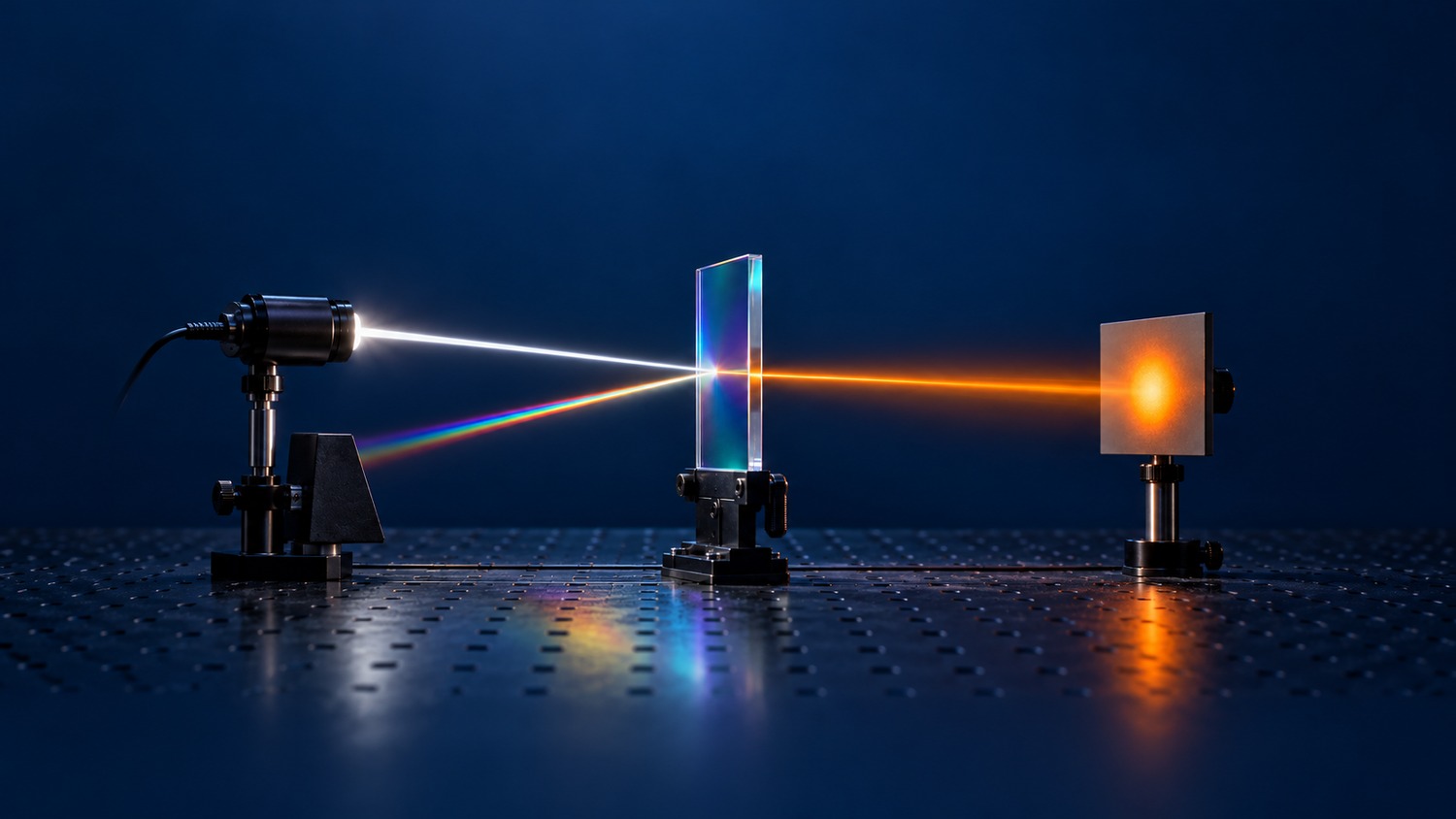
A shortpass (SP) filter transmits a specified range of shorter wavelengths while suppressing longer wavelengths. A 700 nm edge may separate visible light from near-infrared radiation; a 500 nm edge selects a much shorter portion of the visible spectrum. Neither description guarantees transmission down to arbitrarily short wavelengths.
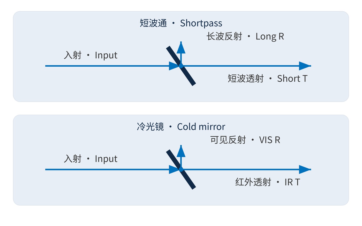
Identify the useful output port first. A shortpass filter is defined by its transmitted light. A cold mirror normally reflects visible light and transmits infrared, so its useful illumination leaves through the reflected port. Fig. 1 compares these complementary arrangements. Their similar appearance does not make them interchangeable.
Dielectric multilayers divide the spectrum through interference. Absorbing materials can also suppress longer wavelengths, but the rejected energy heats the component. At each wavelength, under the same measurement conditions:
$$T(\lambda)+R(\lambda)+A(\lambda)=1$$
Define the edge criterion explicitly: absolute 50% transmission and half the reference passband transmission are different thresholds. Center wavelength (CWL) and full width at half maximum (FWHM) describe bandpass filters; they do not replace the passband, transition region and stopband of a single-edge filter. Angle of incidence (AOI), polarization and beam cone also affect the edge.
Optical density (OD) expresses leakage using fractional transmission, not a percentage:
$$\mathrm{OD}(\lambda)=-\log_{10}T(\lambda)$$
OD4 means 0.01% transmission, but only within its specified wavelength interval. Fig. 2 illustrates why a transition allowance is necessary between the useful signal and unwanted radiation. Its calculated curve is an illustrative response, not a coating prediction or a product measurement.
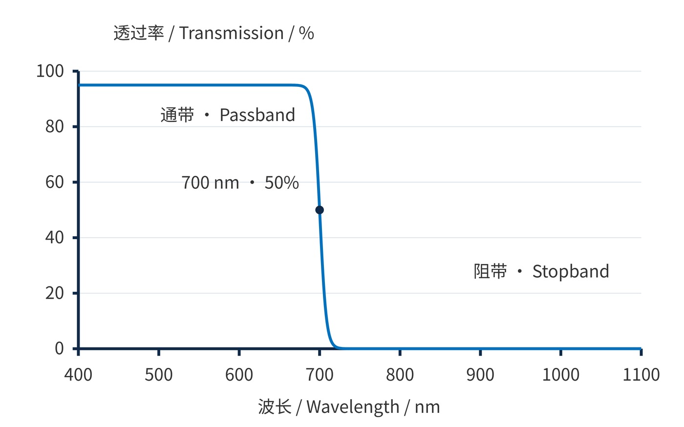
Start with the signal spectrum, unwanted spectrum and detector response. One discussion target could be: AOI 0°, minimum transmission 90% over 420–650 nm, a 700 ± 5 nm edge, and pointwise OD≥4 over 750–1100 nm. These are example requirements, not a catalog specification. The intervening 650–750 nm region needs its own limits.
| System input | Specification to record | Risk if omitted |
|---|---|---|
| Useful signal | 420–650 nm; minimum transmission 90% | Loss at the red end |
| Unwanted light | 750–1100 nm; pointwise OD≥4 | Detector still receives leakage |
| Beam geometry | AOI, cone angle and polarization | Shifted or split edge |
| Mechanical and thermal load | Clear aperture, thickness, power and cooling | Clipping, focus shift or overheating |
If unwanted light is 1000 times stronger than the signal, 0.01% leakage still equals 10% of the original signal. Weight the source spectrum by transmission and detector response before deciding whether the blocking is sufficient. Acceptance measurements must use the operating geometry and enough instrumental dynamic range to verify the requested OD.
Color imaging and machine vision. Silicon detectors respond beyond the visible spectrum. Suppressing near-infrared light can reduce color contamination, although it cannot repair gaps in the illumination spectrum or replace white balance. A task using 850 nm illumination needs a different spectral decision.
Fluorescence excitation cleanup. When excitation is shorter in wavelength than emission, an SP filter in the excitation branch can reduce the source’s long-wavelength tail. Putting it in the emission collection branch may reject the desired fluorescence. Emission filtering and spatial isolation remain necessary.
Illumination heat management. Reflective infrared rejection redirects energy toward a suitable absorber; an absorbing filter retains the load and needs thermal assessment. A cold mirror instead reflects useful visible light while infrared passes toward a heat receiver. A warm-tinted screen is a way to indicate heating: infrared radiation itself is invisible.
A complete selection accounts for retained signal, residual background and the destination of rejected energy. All three should be measurable under the actual operating conditions.
Technical references: the RP Photonics Encyclopedia entries on dichroic transmission and reflection conventions, and on cold-mirror heat separation.
 365nm Narrow Bandpass Filter | Ø50mm | T>90%
OT-HBP3659050
365nm Narrow Bandpass Filter; FWHM 10nm; transmission >90%; blocking OD5; size Ø50mm; AOI 0°.
 450nm Narrow Bandpass Filter | Ø50mm
OT-HBP4509050
450nm Narrow Bandpass Filter; FWHM 10nm; transmission >90%; blocking OD5; size Ø50mm; AOI 0°.
 525nm Narrow Bandpass Filter | Ø50mm
OT-HBP5259050
525nm Narrow Bandpass Filter; FWHM 10nm; transmission >90%; blocking OD5; size Ø50mm; AOI 0°.
Send us your drawing and spectral targets — an engineer replies with a feasibility check and quotation within one business day.