Original content by the OOTEE Optics editorial team, drawn from first-hand production line and inspection data. Please credit the source when republishing.
Given limits in expertise and test conditions, the theories, parameters and conclusions here carry no guarantee of absolute accuracy. For technical learning and exchange only - never the sole basis for design, acceptance or selection. Corrections welcome.

A spectrophotometer can report many decimal places while retaining a systematic error. Instrument calibration relates wavelength and photometric indications to reference values with stated uncertainties. It establishes evidence for errors and corrections. Adjustment and a decision about fitness for use are separate activities.
A baseline establishes a current reference condition; it does not establish wavelength or photometric accuracy. Fig. 1 separates the two questions: whether a feature appears at the correct wavelength, and whether the reported light level is correct. Repeatable readings can still be biased.
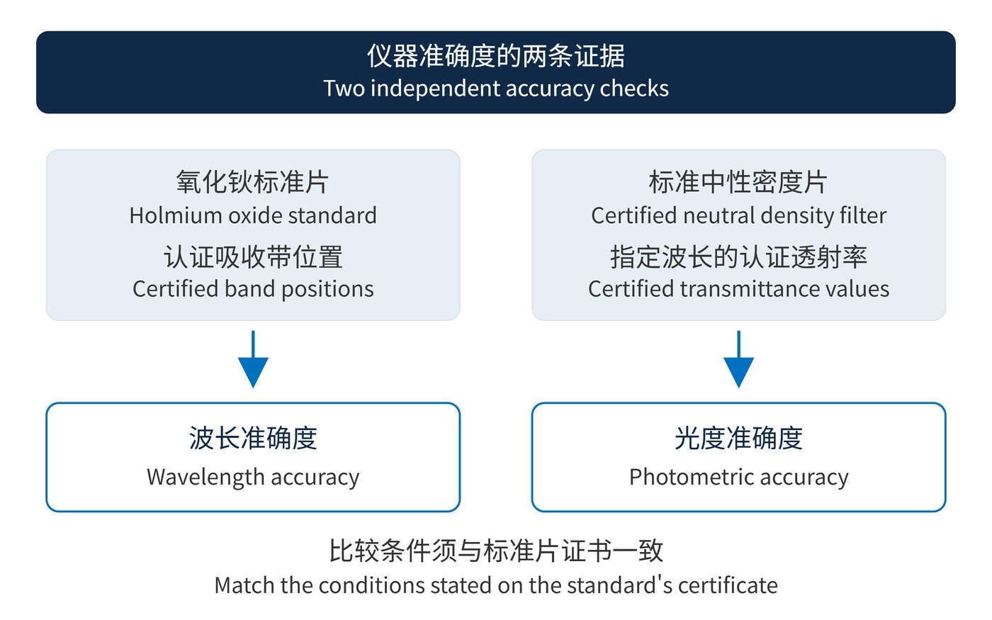
A holmium oxide glass standard provides absorption bands whose transmittance minima can be compared with certified wavelengths. Use the values and spectral bandwidth conditions on the individual certificate. Values for glass and solution standards are not interchangeable. Peak-location algorithms, sampling intervals and spectral bandwidth affect the comparison; a small sampling interval alone does not establish high optical resolution.
$$\Delta\lambda=\lambda_{\mathrm{ind}}-\lambda_{\mathrm{ref}}$$
This convention defines error as indication minus reference. An indication 0.3 nm above its reference requires a correction of the opposite sign, but one point cannot establish a uniform offset across the instrument's range. NIST's holmium oxide glass study documents wavelength stability; the standard's certificate remains the basis for its applicable conditions.
Certified neutral density filters test the photometric scale at specified wavelengths. Compare measured transmittance with the certified value, or express the result as optical density (OD), using fractional transmittance:
$$\mathrm{OD}=-\log_{10}T,\qquad T=\frac{I_{\mathrm{out}}}{I_{\mathrm{in}}}$$
Thus 10% transmittance corresponds to OD1 and 1% to OD2. Reference levels should span the working range. Passing a high-transmittance check does not validate low-transmittance readings or establish OD6 capability. A nominal attenuation specification for a general-purpose neutral density filter is not an individually certified reference value.
Start with the wavelengths, spectral bandwidth, photometric range and permissible errors required by the intended work. For readings near 550 nm and 10% transmittance, seek appropriate certified points near those conditions. This illustrates matching reference points to use, rather than a universal acceptance criterion. Aperture, orientation and temperature conditions must also suit the instrument.
The US National Institute of Standards and Technology (NIST) or China's National Institute of Metrology (NIM) may provide an upstream reference. Metrological traceability requires a documented, unbroken calibration chain with uncertainty contributions at every link. It is a property of a measurement result, rather than an institution's name on a certificate. NIM's spectral neutral-material calibration capability must likewise be assessed against the required quantity and range.
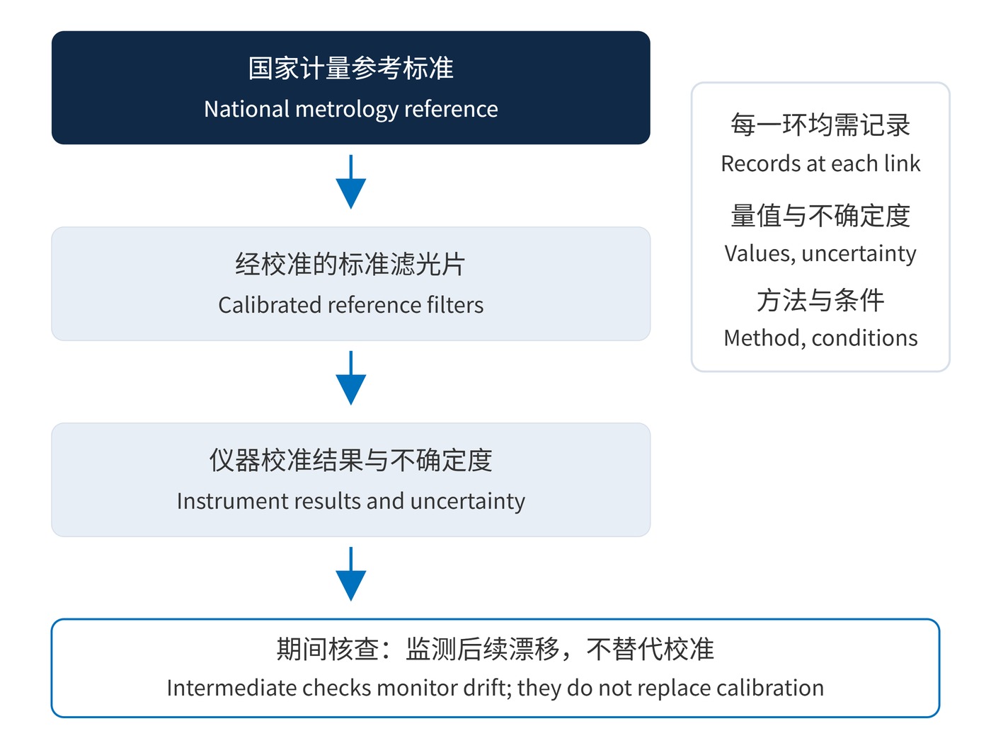
Fig. 2 shows the records that must connect the chain. When using an accredited laboratory, check that its scope includes the relevant quantities, ranges and capabilities. Request the following information rather than accepting a pass statement alone.
Applicability matters as much as the existence of a certificate. A result at one wavelength supports that point under the recorded conditions; extending it to another wavelength or bandwidth requires justification. Likewise, results obtained with one optical arrangement should not automatically be assigned to a different arrangement. These boundaries should be clear before commissioning calibration.
| Certificate information | What to request |
|---|---|
| Identity and status | Instrument and standard identifiers, calibration date, results before and after adjustment |
| Method and conditions | Method version, wavelength points, spectral bandwidth, temperature and measurement geometry |
| Values and uncertainty | Reference values, indications, errors or corrections, expanded uncertainty and its factor k |
| Traceability and decisions | Upstream standards and certificate identifiers; limits and decision rule if conformity is stated |
For instruments supporting incoming inspection, development comparisons or quality release, set intervals according to measurement risk. An initial internal proposal might be 12 months, subject to review; it is not a universal requirement. Workload, environment, drift history and the consequences of error determine whether an interval should change. ILAC-G24 supports continuing review using equipment performance records.
Intermediate checks monitor selected wavelength and photometric points using stable standards, recorded trends and predefined limits. They do not replace full calibration. Repairs, relevant component changes or relocation warrant assessment of whether earlier calibration is needed. A failed check should stop release of affected results, trigger investigation and prompt review of data since the last trustworthy check.
Retaining results before adjustment is particularly useful here: they help establish whether earlier measurements may have been affected. Results after adjustment describe the restored state, but cannot by themselves reconstruct the instrument's previous performance.
Agreement between repeated readings demonstrates repeatability, not freedom from bias. An annual pass does not guarantee unchanged performance throughout the year. Manage reference filters according to their certificates and stability evidence; their review requirements need not match the instrument's calibration interval.
Passing wavelength and photometric checks does not establish stray-light performance, spectral bandwidth or every other required characteristic. Confidence applies to defined ranges and conditions with supporting uncertainty. When an error approaches a working limit, use the uncertainty and agreed decision rule to determine whether the instrument remains suitable for that task.
 365nm Narrow Bandpass Filter | Ø50mm | T>90%
OT-HBP3659050
365nm Narrow Bandpass Filter; FWHM 10nm; transmission >90%; blocking OD5; size Ø50mm; AOI 0°.
 450nm Narrow Bandpass Filter | Ø50mm
OT-HBP4509050
450nm Narrow Bandpass Filter; FWHM 10nm; transmission >90%; blocking OD5; size Ø50mm; AOI 0°.
 525nm Narrow Bandpass Filter | Ø50mm
OT-HBP5259050
525nm Narrow Bandpass Filter; FWHM 10nm; transmission >90%; blocking OD5; size Ø50mm; AOI 0°.
Send us your drawing and spectral targets — an engineer replies with a feasibility check and quotation within one business day.



