Original content by the OOTEE Optics editorial team, drawn from first-hand production line and inspection data. Please credit the source when republishing.
Given limits in expertise and test conditions, the theories, parameters and conclusions here carry no guarantee of absolute accuracy. For technical learning and exchange only - never the sole basis for design, acceptance or selection. Corrections welcome.
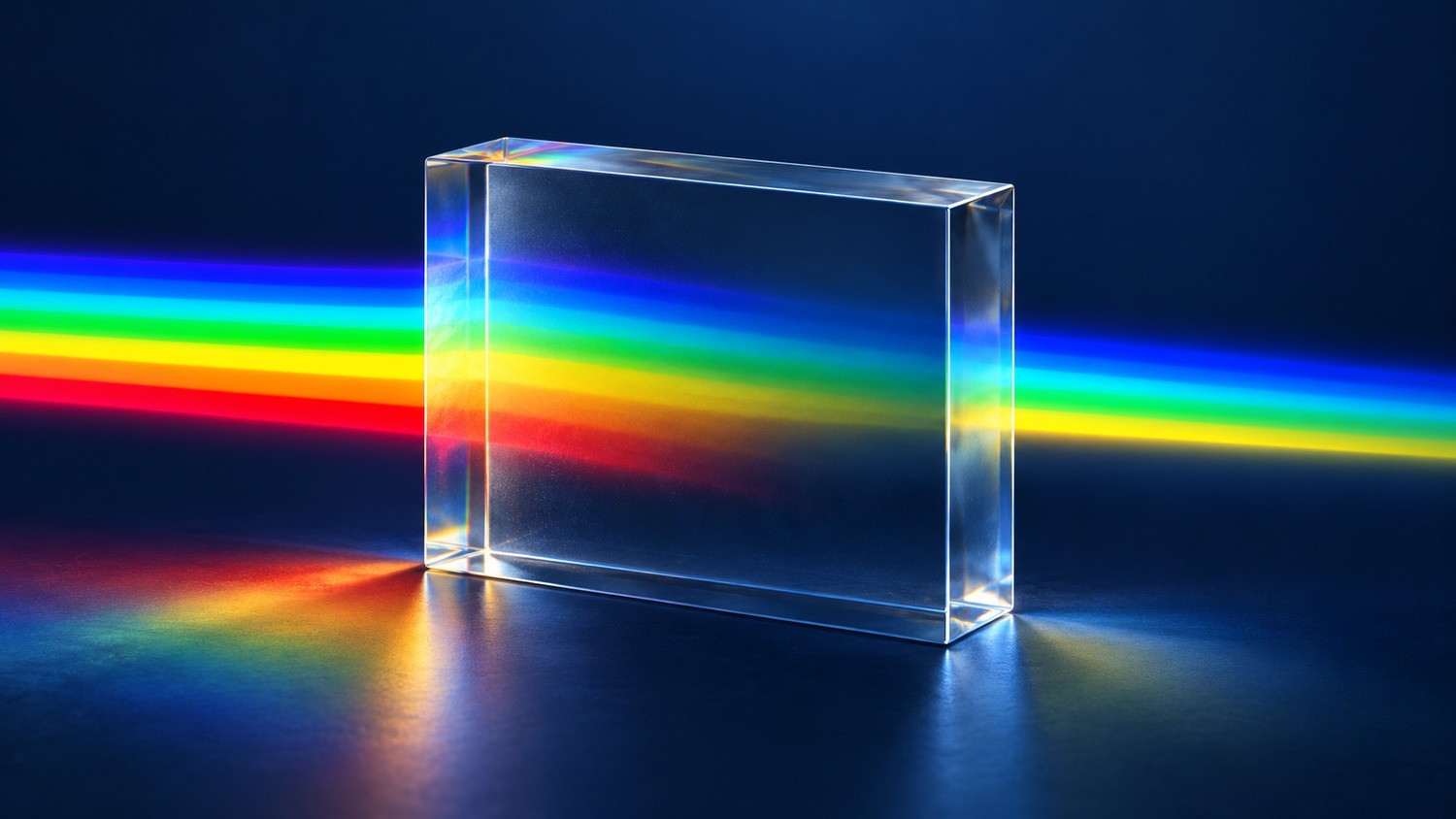
A coating can transmit a wavelength that its substrate cannot carry efficiently. Energy absorbed in the bulk becomes heat, reducing the finished filter's transmission toward the long wavelength end. This material limit is distinct from a coating's designed spectral edge.
Absorptance is the fraction of incident power absorbed by a particular sample. The absorption coefficient describes attenuation per unit path length inside the material. A transparency limit therefore needs both a thickness and a transmission threshold. The figure uses visible colours to illustrate spectral attenuation; it is not a measured spectrum of a specific substrate.
For homogeneous material with linear absorption and negligible scattering, internal transmittance follows the Beer–Lambert law. It excludes surface reflection. Here $\alpha$ is the absorption coefficient and $d$ is the internal path length, expressed in compatible units.
$$T_{\mathrm{int}}(\lambda)=\exp[-\alpha(\lambda)d]$$
Lattice vibrations and multiphonon processes commonly set the intrinsic infrared absorption edge. Impurities can introduce additional bands within the transparency window. Hydroxyl-related absorption in fused silica illustrates why a material name alone cannot specify infrared performance: grade and impurity content matter.
Fig. 1 separates bulk absorption from reflection at an interface. An antireflection coating reduces reflection but cannot remove intrinsic bulk absorption. For a sample without scattering or luminescence, transmittance $T$, reflectance $R$, and absorptance $A$ obey:
$$T(\lambda)+R(\lambda)+A(\lambda)=1$$
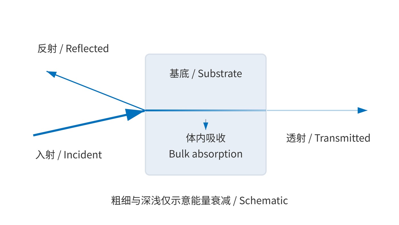
Defining an absorption edge at 50% internal transmission gives $\alpha(\lambda_{50})d=\ln 2$. Where absorption rises monotonically with wavelength, increasing thickness moves this threshold toward shorter wavelengths. Fig. 2 shows increased path loss, rather than a shift in coating center wavelength.
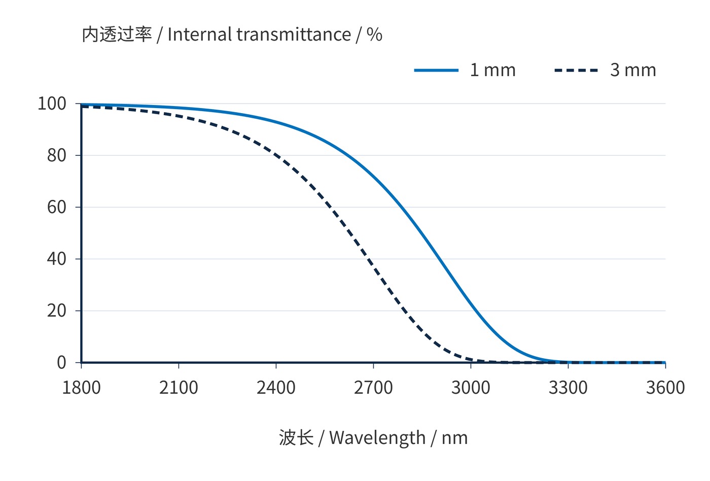
The model uses $\alpha(\lambda)=0.01\exp[(\lambda-2000\,\mathrm{nm})/(200\,\mathrm{nm})]\,\mathrm{mm}^{-1}$ at normal incidence and constant temperature, excluding surface reflection. Calculations use 1 nm spacing. The 50% points are approximately 2848 nm for 1 mm and 2628 nm for 3 mm. Neither value is a glass specification.
Start with the required wavelength interval and minimum finished transmission. A requirement of at least 85% across 2000–2100 nm must be checked throughout that interval at the final thickness. If $\alpha=0.10\,\mathrm{mm}^{-1}$ at 2100 nm, a 3 mm substrate has only 74.1% internal transmission there. Reducing surface reflection cannot bring it to 85%.
| Input | Conditions to specify |
|---|---|
| Material | Grade, impurity control, temperature range |
| Geometry | Finished thickness, tolerance, internal path length |
| Spectrum | Passband, minimum transmission, long wavelength blocking range |
| Measurement | Internal or external transmission, resolution, noise floor |
For bandpass filters, specify center wavelength (CWL), full width at half maximum (FWHM), optical density (OD), and angle of incidence (AOI) separately. CWL 2050 nm, FWHM 100 nm, and AOI 0° do not establish OD6 blocking over 2500–3000 nm. Oblique incidence also changes the bulk path length; use the refracted internal angle in that calculation.
Near-infrared spectrometers lose signal near a substrate absorption edge. Wavelength-dependent attenuation can also bias quantitative results. Calibration should represent the actual thickness and operating temperature, but it cannot recover lost photons.
In broadband illumination and thermal-radiation systems, substrate absorption may suppress unwanted long wavelength background. The absorbed power remains in the optic, however, creating a thermal load. Check source spectral power, heat removal, and leakage across the complete blocking interval before relying on absorption as part of the filtering strategy.
Acceptance data should connect material grade, thickness, temperature, wavelength range, and threshold in one specification. That connection makes bulk loss distinguishable from coating performance.
Reference: the IUPAC definition of the Beer–Lambert law; specific material curves should come from supplier window data for the stated grade and thickness.
 365nm Narrow Bandpass Filter | Ø50mm | T>90%
OT-HBP3659050
365nm Narrow Bandpass Filter; FWHM 10nm; transmission >90%; blocking OD5; size Ø50mm; AOI 0°.
 450nm Narrow Bandpass Filter | Ø50mm
OT-HBP4509050
450nm Narrow Bandpass Filter; FWHM 10nm; transmission >90%; blocking OD5; size Ø50mm; AOI 0°.
 525nm Narrow Bandpass Filter | Ø50mm
OT-HBP5259050
525nm Narrow Bandpass Filter; FWHM 10nm; transmission >90%; blocking OD5; size Ø50mm; AOI 0°.
Send us your drawing and spectral targets — an engineer replies with a feasibility check and quotation within one business day.



