Original content by the OOTEE Optics editorial team, drawn from first-hand production line and inspection data. Please credit the source when republishing.
Given limits in expertise and test conditions, the theories, parameters and conclusions here carry no guarantee of absolute accuracy. For technical learning and exchange only - never the sole basis for design, acceptance or selection. Corrections welcome.
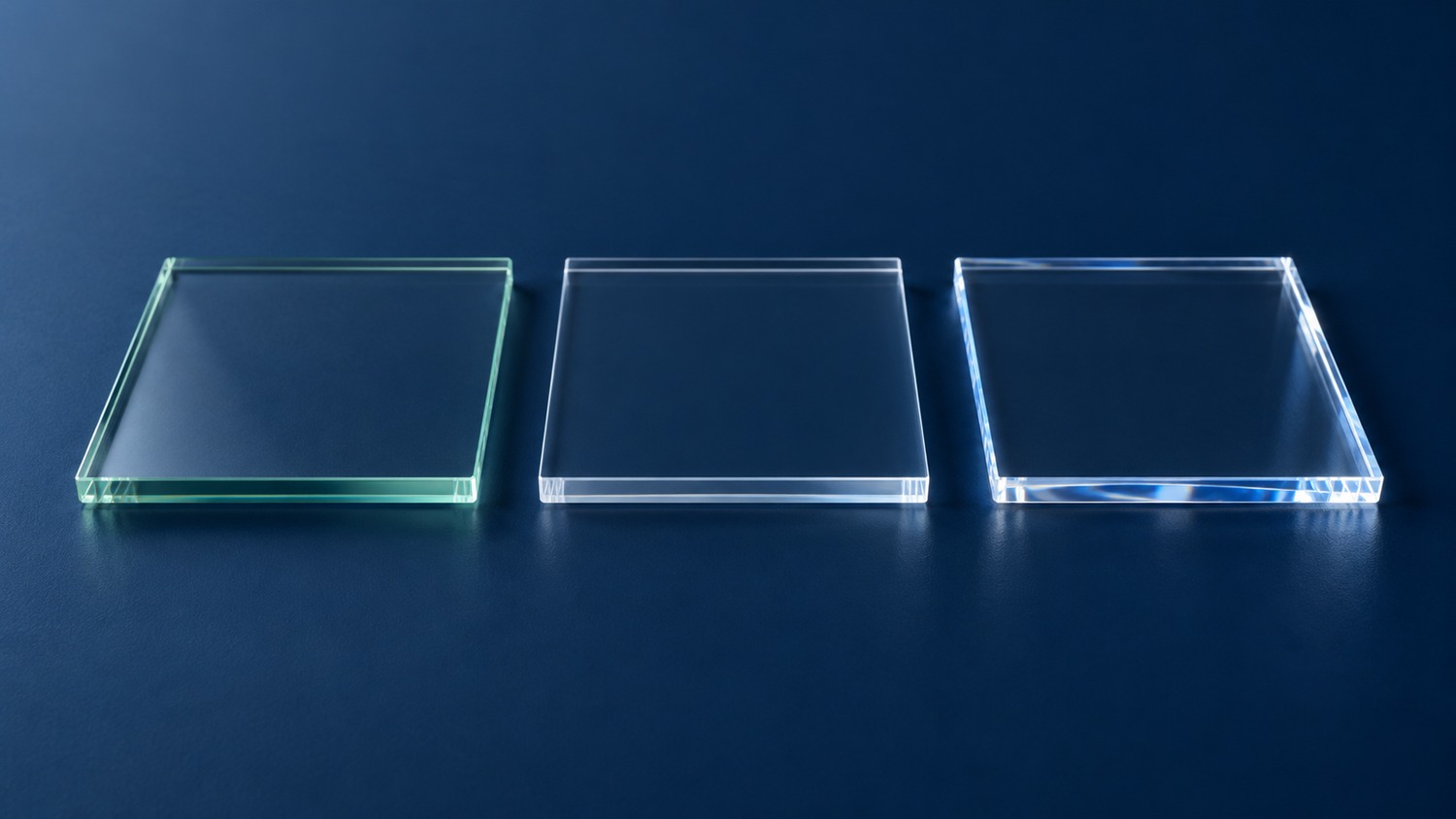
A substrate carries the coating, but also affects throughput, heat flow and mechanical stability. Choosing among optical glass, fused silica and sapphire therefore starts with system constraints. This comparison focuses on qualification and mounting rather than a general catalogue of optical materials.
Optical glass denotes a family: a purchase specification needs an exact grade. Fused silica is amorphous silicon dioxide, distinct from birefringent crystalline quartz. Sapphire is single-crystal aluminium oxide, normally colourless in optical use. Its crystallographic orientation belongs on the drawing. Visual clarity alone cannot establish any of these identities.
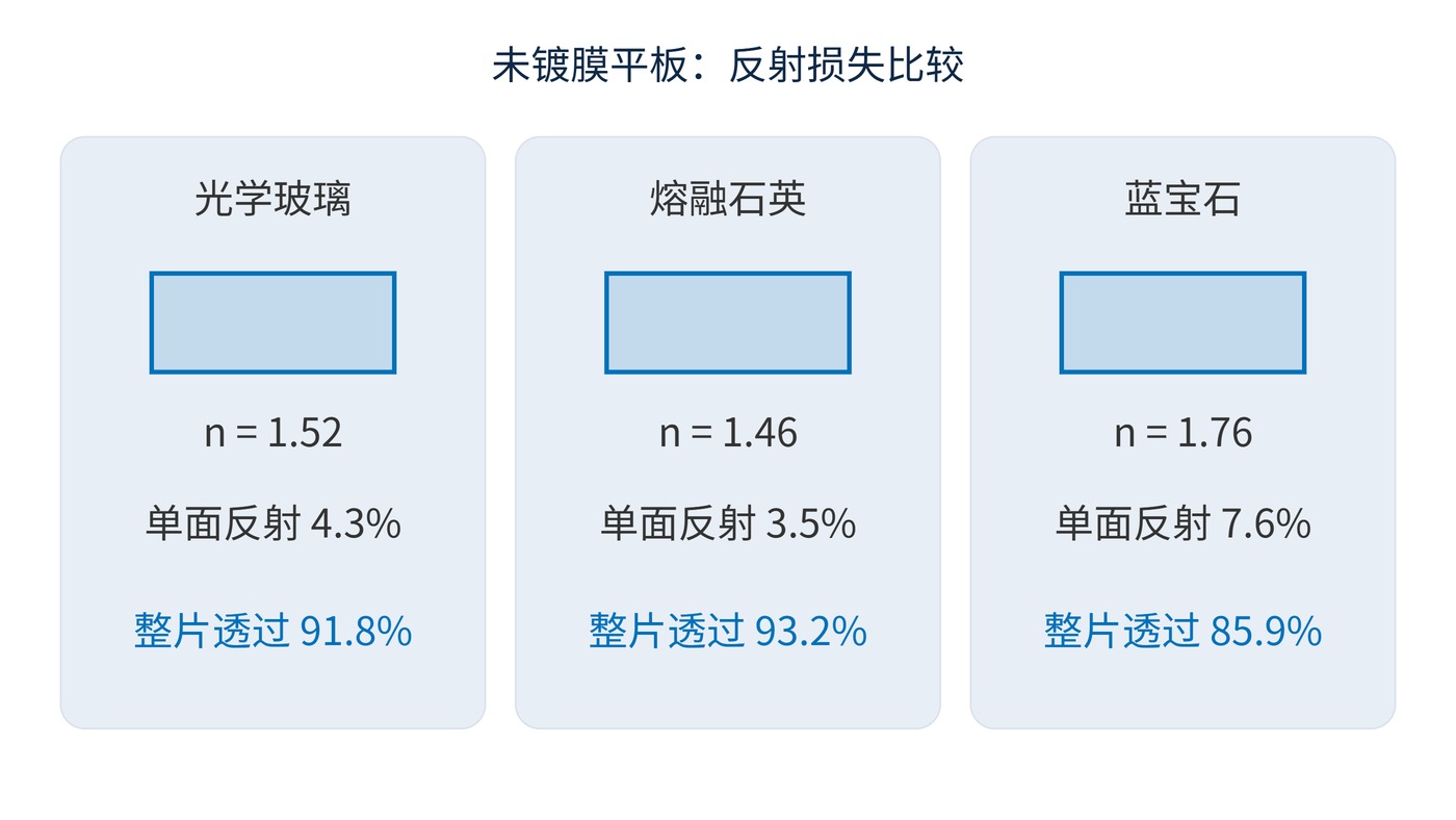
Surface reflection, bulk absorption and scattering all reduce transmission. For an uncoated, nonabsorbing plate in air at normal incidence, including incoherent internal reflections:
$$R=\left(\frac{n-1}{n+1}\right)^2,\qquad T=\frac{1-R}{1+R}$$
Here $n$ is refractive index and $R$ is single-surface reflectance. Fig. 1 uses representative indices of 1.52, 1.46 and 1.76, giving plate transmission of approximately 91.8%, 93.2% and 85.9%. These are comparative calculations, not measured spectra or coated-part guarantees. Sapphire requires an orientation-dependent index.
Free thermal expansion follows the local approximation:
$$\Delta L=\alpha L_0\Delta T$$
A 25 mm fused-silica part heated by 30 °C expands by about 0.39 μm using $0.52\times10^{-6}\ \mathrm{K^{-1}}$, a representative coefficient over 5–35 °C. This limited-range estimate is not a high-temperature prediction. Verify the coefficients against grade-specific supplier data.
Low expansion limits dimensional change; thermal conductivity helps equalise temperature. Neither alone predicts distortion under absorbed power. Sapphire has directional thermal properties, while mount restraint and coating stress can dominate either material's behaviour.
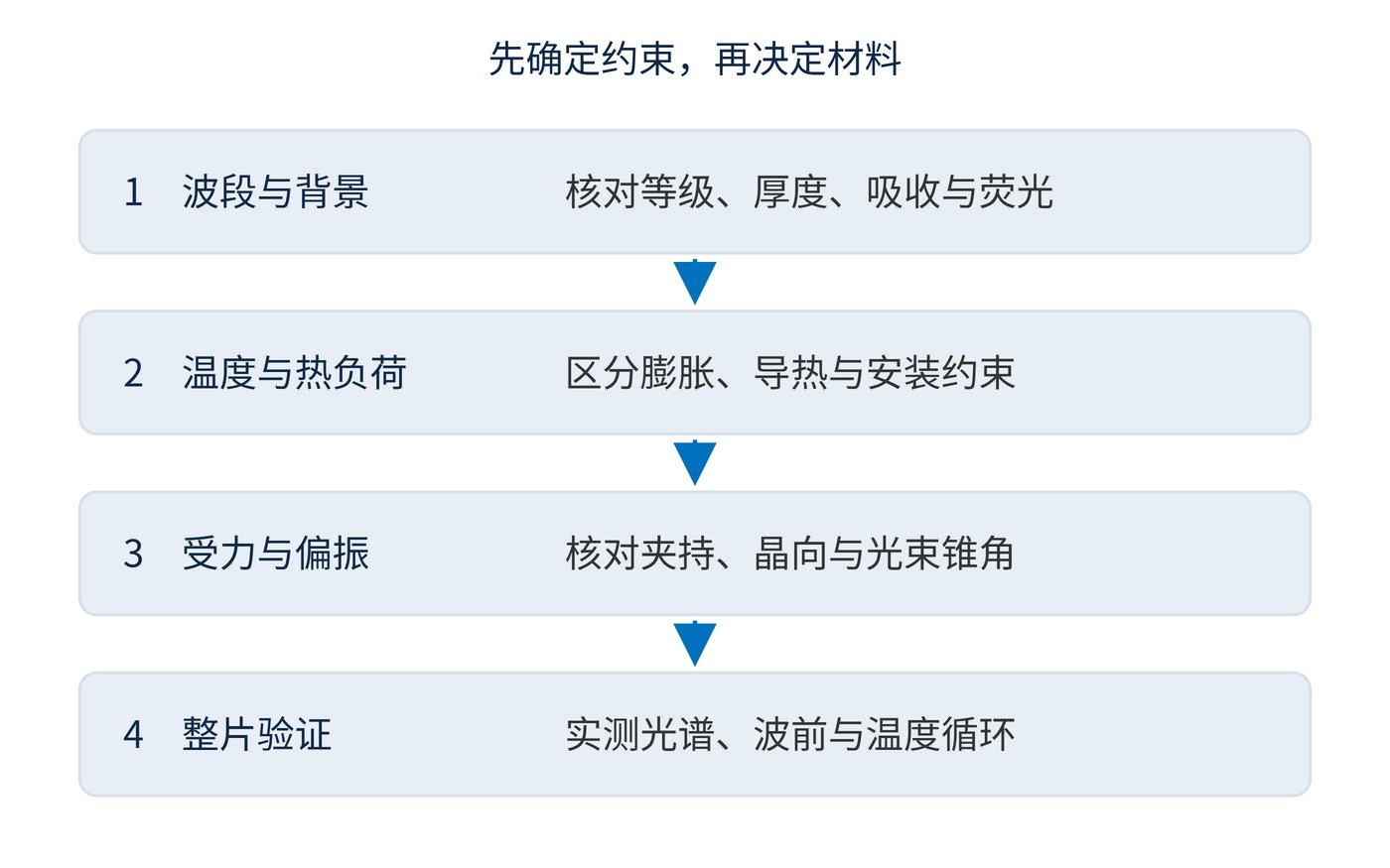
Define wavelength range, thickness, aperture, power density, temperature and mounting before choosing a material. Fig. 2 outlines a risk-based sequence.
| Candidate | Useful starting point | Information to request |
|---|---|---|
| Optical glass | Routine visible optics; economical processing | Grade, internal transmission at thickness, homogeneity |
| Fused silica | UV work; low expansion; low background | UV/IR grade, suitable hydroxyl content, fluorescence test |
| Sapphire | Abrasion exposure; protective windows; heat spreading | Crystal orientation, polarisation, mounting and coating compatibility |
A filter with centre wavelength (CWL) 780 nm, full width at half maximum (FWHM) 20 nm and optical density (OD) 6 still needs a blocking interval and angle of incidence (AOI), for example 0°. Those coating targets do not determine the substrate. Start with suitable optical glass for moderate ambient conditions; examine fused silica when thermal cycling or wavefront stability dominates, and sapphire when abrasion or thermal gradients justify its additional constraints.
Freeze grade, aperture, thickness, transmitted wavefront and mounting condition together. Request internal and external transmission separately. Bare and coated witness samples from the same material batch can help distinguish substrate losses from coating effects.
Internal transmission describes propagation through the material with surface reflection excluded. External transmission includes the interfaces. Comparing one supplier's internal value with another's finished-window value can therefore produce a misleading ranking. The quoted thickness and wavelength interval must match the intended part, especially near an absorption edge.
UV-grade fused silica is a useful candidate for UV detection, subject to absorption and background measurements at the operating wavelengths. In weak-fluorescence detection, test a blank with the actual excitation, collection band and exposure; “silica” does not mean zero background.
Enclosed industrial imaging may be well served by optical glass. Exposed abrasion-resistant windows may favour sapphire. Polarisation-sensitive instruments must also specify crystal axis and beam cone. Ideal propagation along the optical axis avoids birefringent splitting, but off-axis rays must be analysed separately for the specified crystal axis and cone angle.
For either application, test the optic in its intended holder. A material that performs well as a freely supported coupon can behave differently when bonded or clamped. Temperature cycling should include a return measurement at the starting temperature, so that reversible changes can be distinguished from residual deformation or damage. Keep the measurement aperture and illumination geometry consistent when comparing candidates.
Final acceptance should reproduce AOI, polarisation, temperature and mounting constraints. A material certificate establishes identity; assembled measurements establish performance.
Document those conditions alongside the acceptance results so that a later substrate substitution can be assessed against the same baseline.
 365nm Narrow Bandpass Filter | Ø50mm | T>90%
OT-HBP3659050
365nm Narrow Bandpass Filter; FWHM 10nm; transmission >90%; blocking OD5; size Ø50mm; AOI 0°.
 450nm Narrow Bandpass Filter | Ø50mm
OT-HBP4509050
450nm Narrow Bandpass Filter; FWHM 10nm; transmission >90%; blocking OD5; size Ø50mm; AOI 0°.
 525nm Narrow Bandpass Filter | Ø50mm
OT-HBP5259050
525nm Narrow Bandpass Filter; FWHM 10nm; transmission >90%; blocking OD5; size Ø50mm; AOI 0°.
Send us your drawing and spectral targets — an engineer replies with a feasibility check and quotation within one business day.



