Original content by the OOTEE Optics editorial team, drawn from first-hand production line and inspection data. Please credit the source when republishing.
Given limits in expertise and test conditions, the theories, parameters and conclusions here carry no guarantee of absolute accuracy. For technical learning and exchange only - never the sole basis for design, acceptance or selection. Corrections welcome.
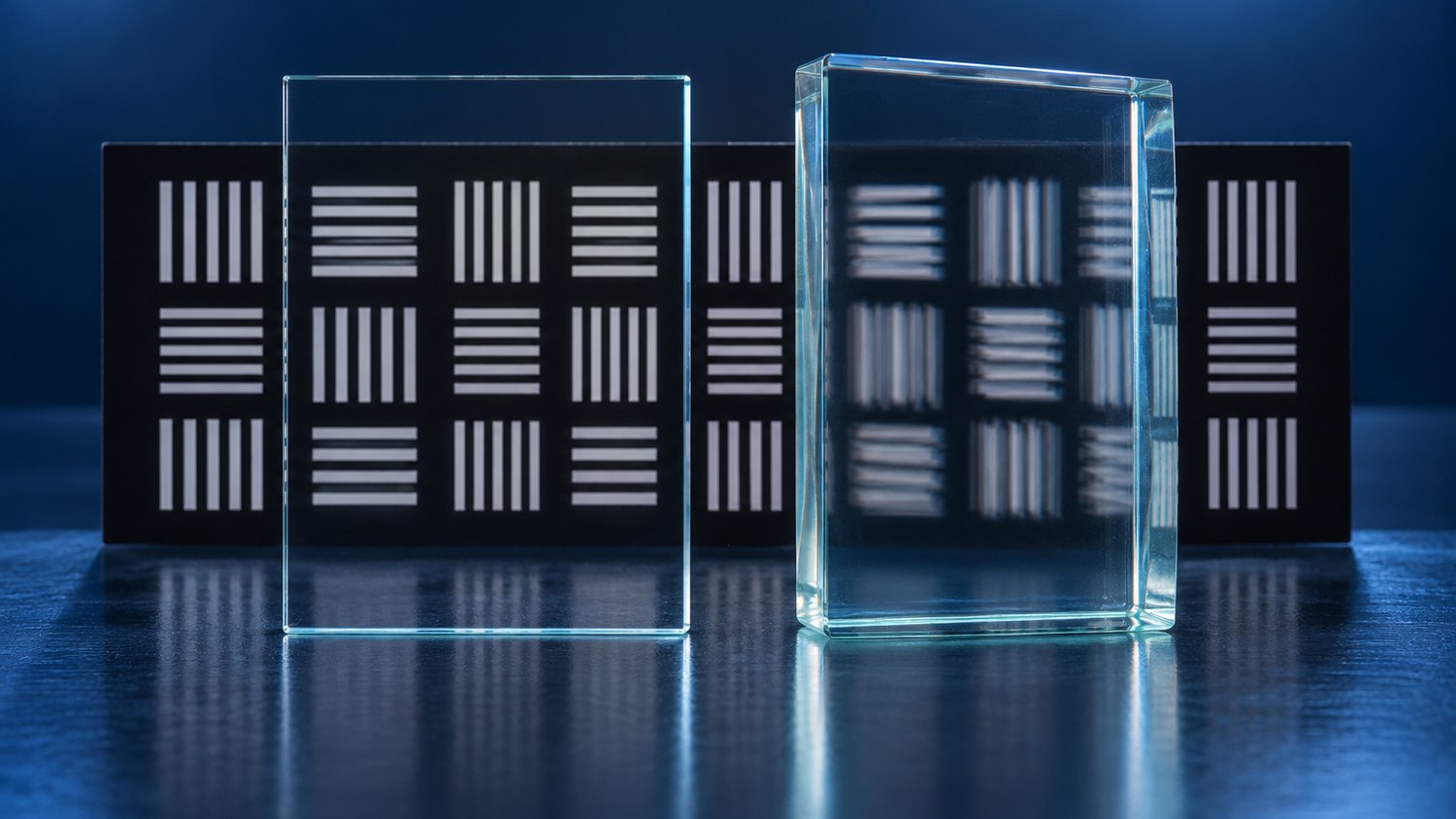
A filter can meet its spectral specification and still alter the image delivered to a sensor. Substrate thickness affects focus and aberrations; parallelism specifies the angle between the surface normals. The imaging consequences include focus displacement, beam steering and, when secondary reflections are significant, ghosts.
The useful distinction is between a collimated section and a converging beam. A shifted image is also different from a blurred one. The illustration is conceptual; neither thickness nor wedge alone guarantees visible doubling.
For a plane-parallel plate normal to a paraxial converging beam in air, the focus moves downstream by approximately:
$$\Delta z \approx t\left(1-\frac{1}{n}\right)$$
Here, $t$ is thickness and $n$ is refractive index. A $1.00\,\mathrm{mm}$ plate with $n=1.52$ gives about $0.342\,\mathrm{mm}$ of shift. A $0.05\,\mathrm{mm}$ thickness error changes focus by roughly $17\,\mathrm{\mu m}$. If the lens design already includes a window, budget the change from that design.
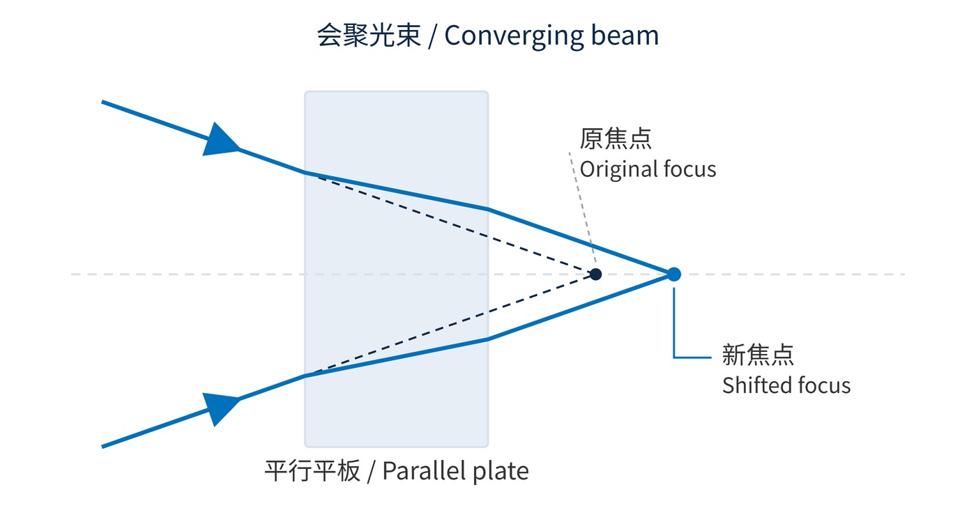
Fig. 1 isolates paraxial defocus. Refocusing removes its main contribution, but marginal rays experience a different shift, leaving spherical aberration in a fast beam. Tilting the plate can also introduce astigmatism.
A small wedge behaves approximately as a thin prism. Near normal incidence in air:
$$\delta \approx (n-1)\alpha,\qquad \Delta x \approx f\delta$$
Angles are in radians. The second relation applies to a wedge in collimated space before an imaging lens of effective focal length $f$. With $n=1.52$, $\alpha=1^{\prime}$ and $f=50\,\mathrm{mm}$, displacement is about $7.6\,\mathrm{\mu m}$, or 2.2 pixels at $3.45\,\mathrm{\mu m}$ pitch. A plate near the sensor requires its actual propagation geometry instead.
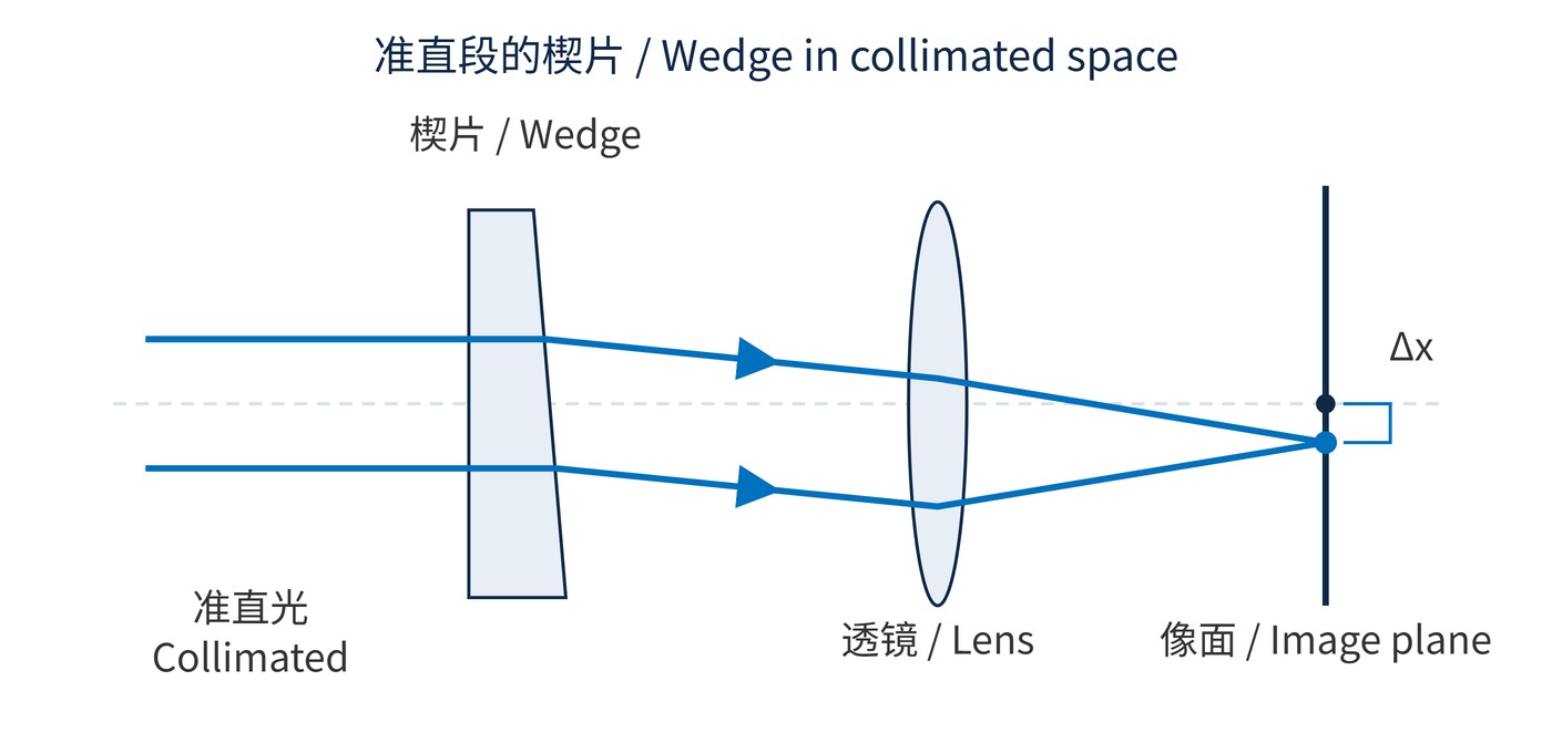
As Fig. 2 shows, steering alone need not reduce sharpness. Visible ghosts require a secondary reflected path with sufficient intensity and separation. Parallelism also says nothing about surface curvature, material homogeneity or mounting stress.
Start with pixel pitch, aperture, field, plate location and available focus travel. Preserve the window conditions assumed by the lens design. In a fast converging beam, include the substrate in the optical model and evaluate modulation transfer function (MTF) across the field.
| Budget | Illustrative requirement | Check |
|---|---|---|
| Assembly focus | ±10 μm; n=1.52 | About ±0.029 mm thickness if it consumes the entire budget |
| Channel registration | 3.45 μm shift; f=50 mm | About ≤27 arcseconds wedge before reserving alignment margin |
| Residual aberration | Operating aperture and full field | MTF after refocusing, including field edges |
These are budget examples, not universal purchase grades. Specify thickness measurement location, variation across the clear aperture, angular units and inspection aperture. Test the coated part in its intended mount. Compare fixed-focus images with best-focus images to distinguish recoverable defocus from residual degradation.
The focus allowance in the table is allocated entirely to thickness. In a real assembly, sensor placement, lens seating and temperature may consume part of it, so the permitted thickness variation becomes smaller. Likewise, the wedge estimate is a first-order registration limit, not a complete tolerance analysis. Keep the wedge orientation consistent when comparing replacements, since rotating the plate changes the direction of the displacement.
Keep spectral acceptance separate: for example, center wavelength (CWL) 780 nm, full width at half maximum (FWHM) 20 nm, optical density (OD) 6 over a defined blocking range, and angle of incidence (AOI) 0° with the actual light cone specified. These values do not certify imaging performance.
Machine vision may retain sharp edges while a replacement plate shifts calibrated coordinates. Check registration, magnification and distortion. Multichannel fluorescence systems need channel-specific best focus and spatial alignment, alongside spectral transmission.
Microscopy and fast optics benefit from evaluating a collimated location first, while checking lateral displacement, spectral angle effects and stray reflections. For a fixed sensor-side filter, capture the same target at the center and four corners under unchanged illumination and exposure; record both MTF and focus adjustment.
Use a focus sweep rather than a single image when the result is ambiguous. A similar best-focus contrast with a changed focus setting points toward defocus; lower best-focus contrast calls for further investigation of aberrations, ghosts or mounting deformation. Measure target position as well as contrast, because registration errors can remain after the sharpest image has been recovered.
The focus and image shifts above are paraxial approximations; away from the paraxial regime or at large incidence angles, use actual ray-trace results.
 365nm Narrow Bandpass Filter | Ø50mm | T>90%
OT-HBP3659050
365nm Narrow Bandpass Filter; FWHM 10nm; transmission >90%; blocking OD5; size Ø50mm; AOI 0°.
 450nm Narrow Bandpass Filter | Ø50mm
OT-HBP4509050
450nm Narrow Bandpass Filter; FWHM 10nm; transmission >90%; blocking OD5; size Ø50mm; AOI 0°.
 525nm Narrow Bandpass Filter | Ø50mm
OT-HBP5259050
525nm Narrow Bandpass Filter; FWHM 10nm; transmission >90%; blocking OD5; size Ø50mm; AOI 0°.
Send us your drawing and spectral targets — an engineer replies with a feasibility check and quotation within one business day.



