Original content by the OOTEE Optics editorial team, drawn from first-hand production line and inspection data. Please credit the source when republishing.
Given limits in expertise and test conditions, the theories, parameters and conclusions here carry no guarantee of absolute accuracy. For technical learning and exchange only - never the sole basis for design, acceptance or selection. Corrections welcome.
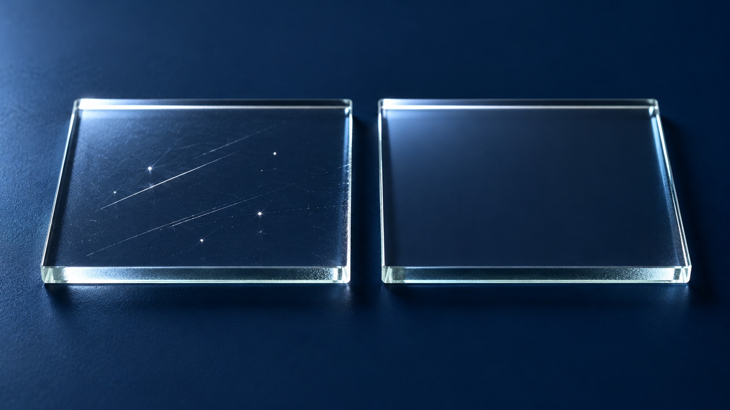
A scratch-dig callout limits local surface imperfections. Under the same inspection standard and conditions, 40-20 is tighter than 60-40. It does not, by itself, promise higher transmission or sharper images. The useful purchasing question is whether the tighter finish addresses a real source of error in the optical system.
A complete requirement identifies the standard revision, inspection area and condition of the delivered surfaces. Without these, two inspectors can reach different acceptance decisions while both believe they followed the drawing.
Under the comparison method in MIL-PRF-13830B, the first number is a scratch comparison grade, not a width in micrometres. The second specifies dig diameter in units of 0.01 mm; irregular digs use the average of maximum length and width. Fig. 1 distinguishes these two meanings.
$$d_{\mathrm{dig}}=N_{\mathrm{dig}}\times0.01\,\mathrm{mm}$$
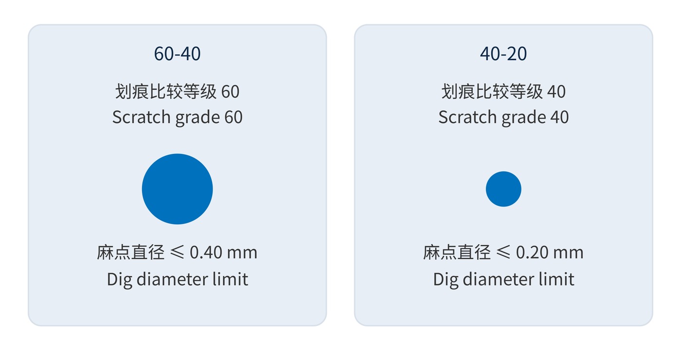
Reducing a circular dig from 0.40 mm to 0.20 mm reduces its geometric area to one quarter. This is a size comparison, not a prediction of total transmission or a fourfold reduction in stray light. Scattering depends on defect shape, location, wavelength and the angles collected by the detector.
$$\frac{A_{20}}{A_{40}}=\left(\frac{0.20\,\mathrm{mm}}{0.40\,\mathrm{mm}}\right)^2=\frac14$$
Acceptance also involves accumulated scratch length and dig population. A photograph can locate a suspect mark but cannot replace inspection with agreed lighting, viewing conditions and comparison standards. Substrate approval before coating does not establish acceptance of the finished coated optic.
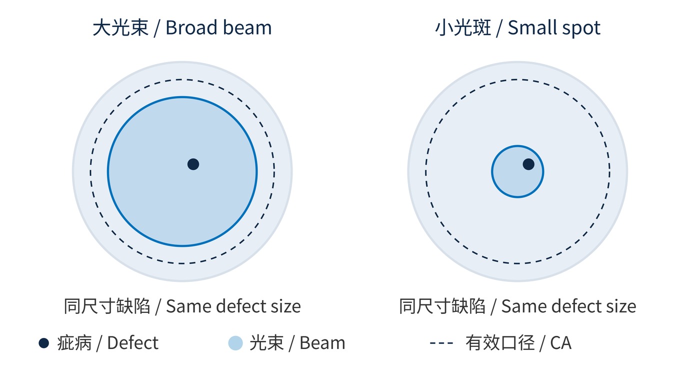
Start with the clear aperture (CA), illuminated footprint and surface position in the optical layout. A defect inside a small spot can matter much more than one outside the working beam, as Fig. 2 illustrates. Proximity to an image plane and strong illumination outside the desired signal also change the risk.
| Operating condition | Starting point | Additional evidence |
|---|---|---|
| Broad beam, away from image planes, modest background | Evaluate 60-40 | Transmission and image uniformity |
| Weak signal with strong background, dark field or near an image plane | Evaluate 40-20 first | Stray light and visible defect artifacts |
| Small spot or high power density | Neither grade alone is sufficient | Local defect limits and damage testing |
Keep spectral requirements separate. An illustrative specification might include centre wavelength (CWL) 780 nm, full width at half maximum (FWHM) 20 nm and angle of incidence (AOI) 0°, with optical density (OD) 6 assigned to an explicit blocking interval. None of these establishes a scratch-dig grade.
A workable drawing could require both finished coated surfaces to meet 40-20 within a 20 mm diameter clear aperture, under MIL-PRF-13830B. Add requirements for coating pinholes, the area outside that aperture, cleaning and dispute inspection. A tighter central zone needs a dimensioned boundary.
Before releasing that drawing, agree which surfaces will be inspected after coating and how removable contamination will be distinguished from permanent damage. Dust can look like a bright dig under grazing illumination. Repeat inspection after the agreed cleaning procedure before recording a permanent defect, and retain its location so a later examination can find the same feature.
For broad-beam machine vision, a 60-40 sample may be a reasonable starting point. Check flat-field images and target contrast before tightening the whole surface. Fluorescence collection and dark-field instruments merit an earlier 40-20 comparison, especially where strong excitation produces localized bright artifacts.
Small-spot laser paths require location-specific limits and independent laser damage qualification. Even 40-20 can permit a defect unsuitable for the illuminated spot. To isolate the benefit of surface quality, compare samples with matching substrate, coating, spectral response, cleanliness and alignment.
Measure the result with the intended source and detector geometry. A detector that collects a wide cone of scattered light may respond differently from one behind a narrow stop. Record background levels as well as useful signal; a small change in average throughput can conceal a localized artifact that matters to the measurement.
Record the inspected surface, aperture, defect locations, comparison standard and reinspection conditions. The engineering acceptance criterion remains whether the agreed surface quality supports the system’s stray-light, imaging and reliability budgets.
References: MIL-PRF-13830B, sections 3.5 and 4.2.2; relevant clauses of ISO 10110-7:2017.
 365nm Narrow Bandpass Filter | Ø50mm | T>90%
OT-HBP3659050
365nm Narrow Bandpass Filter; FWHM 10nm; transmission >90%; blocking OD5; size Ø50mm; AOI 0°.
 450nm Narrow Bandpass Filter | Ø50mm
OT-HBP4509050
450nm Narrow Bandpass Filter; FWHM 10nm; transmission >90%; blocking OD5; size Ø50mm; AOI 0°.
 525nm Narrow Bandpass Filter | Ø50mm
OT-HBP5259050
525nm Narrow Bandpass Filter; FWHM 10nm; transmission >90%; blocking OD5; size Ø50mm; AOI 0°.
Send us your drawing and spectral targets — an engineer replies with a feasibility check and quotation within one business day.



