Original content by the OOTEE Optics editorial team, drawn from first-hand production line and inspection data. Please credit the source when republishing.
Given limits in expertise and test conditions, the theories, parameters and conclusions here carry no guarantee of absolute accuracy. For technical learning and exchange only - never the sole basis for design, acceptance or selection. Corrections welcome.
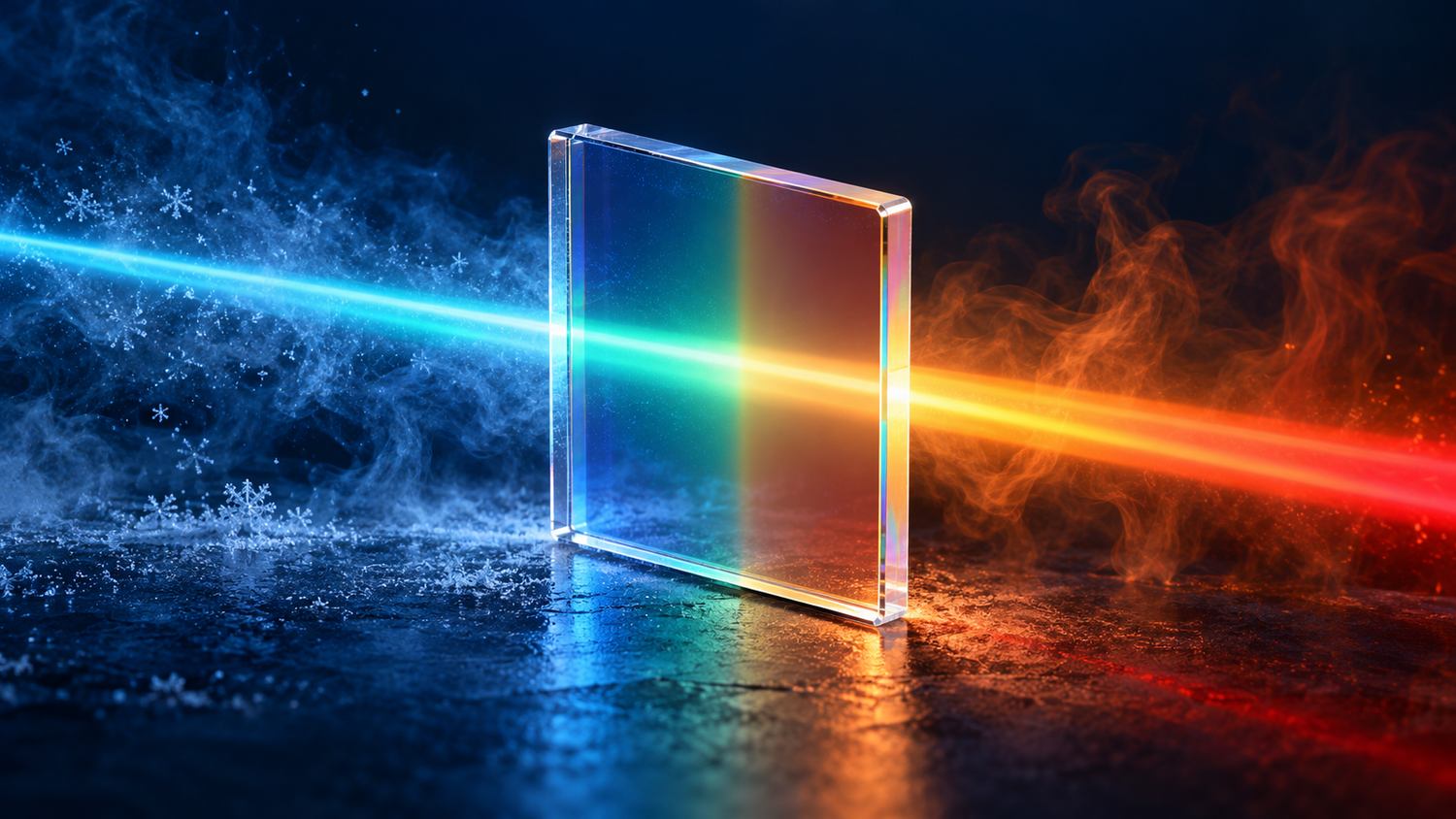
Temperature drift is the movement of a filter’s spectral features as its temperature changes. Center wavelength (CWL) is a useful tracking metric. For a single passband, define it consistently—for example, as the midpoint between the two half-maximum crossings—so peak ripple does not masquerade as motion.
Full width at half maximum (FWHM) describes bandwidth, optical density (OD) specifies attenuation over a stated blocking range, and angle of incidence (AOI) is a controlled test condition. An operating temperature rating alone does not quantify wavelength drift. The cover exaggerates the visible color change; a small shift is generally not apparent to the eye.
Interference depends on optical thickness. Heating changes both refractive index and physical layer thickness, while substrate constraint and coating stress also affect the response. A simplified equivalent optical thickness at normal incidence gives the local approximation:
$$\frac{1}{\lambda_{\mathrm{c}}}\frac{\mathrm{d}\lambda_{\mathrm{c}}}{\mathrm{d}T}\approx\frac{1}{n}\frac{\mathrm{d}n}{\mathrm{d}T}+\frac{1}{d}\frac{\mathrm{d}d}{\mathrm{d}T}$$
Here, $T$ is temperature, and $n$ and $d$ are equivalent index and thickness. A multilayer filter requires a measured assembly-level coefficient rather than a value copied from one bulk material. Heating often produces a red shift, but its sign depends on the coating and substrate.
Within a temperature interval verified to be approximately linear, use reference temperature $T_0$ and coefficient $k_T$:
$$\lambda_{\mathrm{c}}(T)\approx\lambda_{\mathrm{c}}(T_0)+k_T(T-T_0),\qquad k_T=\frac{\Delta\lambda_{\mathrm{c}}}{\Delta T}$$
Keep units explicit: 1 nm/°C equals 1000 pm/°C. As an assumed example, a 780 nm filter at 20 °C with $k_T=+0.010\,\mathrm{nm/^{\circ}C}$ reaches 779.6 nm at −20 °C and 780.4 nm at 60 °C. Its endpoint span is 0.8 nm; its largest displacement from the reference is 0.4 nm.
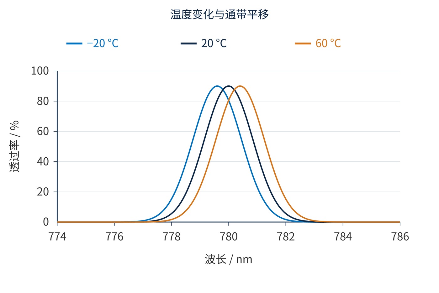
Fig. 1 isolates translation: peak transmission is 90% and FWHM is 2 nm at all three temperatures. This illustrative model explains sensitivity; it is neither a multilayer simulation nor measured product data.
The relevant quantity is the separation between the source wavelength and the passband. Track source and filter temperatures independently. Subtracting their thermal coefficients is valid only when both experience the same temperature change.
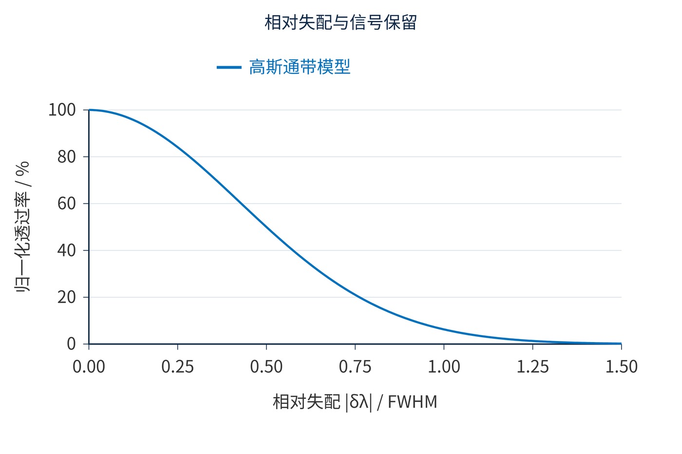
For the Gaussian model, let $\delta\lambda$ be source-to-center mismatch and $w$ the FWHM. Transmission relative to its peak is:
$$\frac{\tau}{\tau_{\mathrm{peak}}}=\exp\!\left[-4\ln 2\left(\frac{\delta\lambda}{w}\right)^2\right]$$
A 0.4 nm mismatch retains about 89.5% of peak transmission with a 2 nm FWHM, but only 64.2% with a 1 nm FWHM. Fig. 2 shows why mismatch divided by bandwidth is more informative than drift alone.
| Acceptance item | Example requirement |
|---|---|
| Reference spectrum | 20 °C; CWL 780 nm; FWHM 2 nm; AOI 0° |
| Thermal coefficient | Maximum absolute value 0.010 nm/°C over −20 to 60 °C |
| Blocking | OD6 over 400–760 nm and 800–1100 nm |
| Repeat measurement | Heating, cooling, and return to 20 °C |
These are example specification clauses, not product claims. Allocate additional margin for manufacturing tolerance, source drift, angular spread, and measurement uncertainty. Verify peak transmission and blocking separately at each temperature.
For a flat-top passband, read transmission at the target wavelength from each temperature-specific spectrum instead of imposing a Gaussian shape. A narrow-line source also needs a linewidth and wavelength-locking allowance. For a broadband signal, integrate the product of source spectrum and filter transmission over wavelength. This distinguishes a displaced band that still passes the useful signal from one that clips a critical spectral feature; the same CWL shift can have very different system consequences.
Outdoor laser receivers require a joint source-and-filter budget. Even a stabilized laser can lose received signal when the filter tracks ambient temperature. Broad fluorescence bands may be less sensitive, yet spectral features near channel edges can still change throughput or crosstalk.
Hold AOI, beam cone angle, and polarization fixed during testing. Place the temperature sensor near the mounted filter and acquire spectra only after sample temperature and spectral position stabilize. Record actual temperature rather than chamber setpoint. Include cold, reference, hot, and return-to-reference measurements; establish soak time from the assembly’s thermal response.
Report recoverable motion separately from residual displacement after returning to the reference temperature. Residual changes warrant investigation of humidity, stress relaxation, or structural effects. Two endpoints provide an average coefficient; they cannot establish linearity or rule out hysteresis.
Tilting a filter is not a universal thermal correction because it also changes polarization response and angular broadening. Acceptance should combine minimum transmission at the target wavelength, OD across the specified blocking bands, and recovery after thermal cycling.
 365nm Narrow Bandpass Filter | Ø50mm | T>90%
OT-HBP3659050
365nm Narrow Bandpass Filter; FWHM 10nm; transmission >90%; blocking OD5; size Ø50mm; AOI 0°.
 450nm Narrow Bandpass Filter | Ø50mm
OT-HBP4509050
450nm Narrow Bandpass Filter; FWHM 10nm; transmission >90%; blocking OD5; size Ø50mm; AOI 0°.
 525nm Narrow Bandpass Filter | Ø50mm
OT-HBP5259050
525nm Narrow Bandpass Filter; FWHM 10nm; transmission >90%; blocking OD5; size Ø50mm; AOI 0°.
Send us your drawing and spectral targets — an engineer replies with a feasibility check and quotation within one business day.



