Original content by the OOTEE Optics editorial team, drawn from first-hand production line and inspection data. Please credit the source when republishing.
Given limits in expertise and test conditions, the theories, parameters and conclusions here carry no guarantee of absolute accuracy. For technical learning and exchange only - never the sole basis for design, acceptance or selection. Corrections welcome.
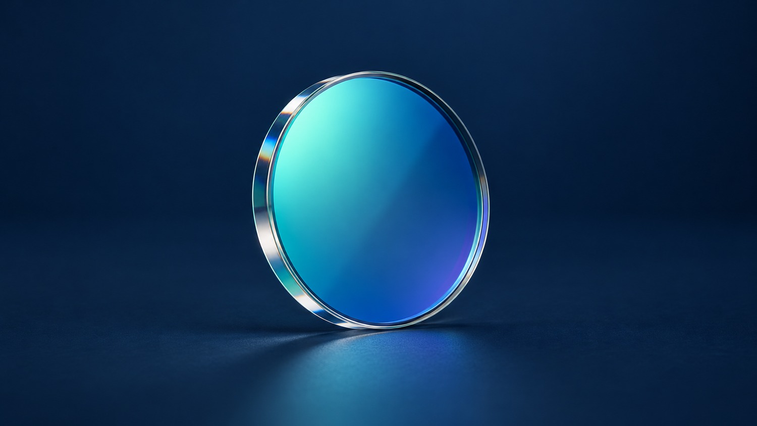
Transmittance tells you how much incident optical power passes through a filter. Reflectance measures the fraction returned into reflected directions. Blocking depth describes how little transmission remains in a specified rejection band. Compare these quantities at the same wavelength and under the same illumination and collection conditions.
Optical density (OD) expresses transmission on a logarithmic scale; it is not an additional energy channel. The practical questions are how much useful signal survives, how much unwanted light leaks through, and where the rejected energy goes.
Fig. 1 separates the energy paths. Strong blocking alone establishes neither high reflectance nor low heating: rejected power may be absorbed.
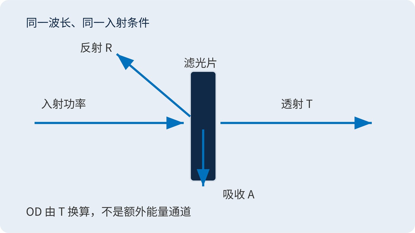
With incident power $P_{\mathrm{in}}$, transmitted power $P_{\mathrm{t}}$ and reflected power $P_{\mathrm{r}}$, define $T=P_{\mathrm{t}}/P_{\mathrm{in}}$ and $R=P_{\mathrm{r}}/P_{\mathrm{in}}$. For a passive, nonluminescent component at steady state, counting all outgoing directions gives:
$$T(\lambda)+R(\lambda)+A(\lambda)=1$$
Here $A$ is absorptance. A detector collecting only the specular beam can miss scattered light, so its measured $1-T-R$ is not necessarily absorption. See the discussion of reflectance and collection geometry. Thermal assessment needs total transmission and reflection, or an independent absorption measurement, with collection geometry and reference conditions documented.
Use fractional transmission, not the numerical percentage, when calculating OD:
$$\mathrm{OD}(\lambda)=-\log_{10}T(\lambda),\qquad T(\lambda)=10^{-\mathrm{OD}(\lambda)}$$
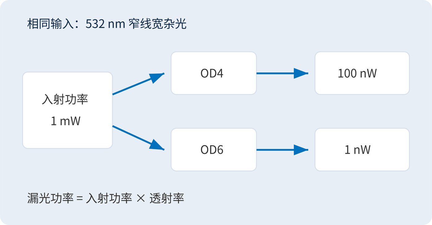
OD6 means $T=10^{-6}$, or 0.0001%; OD4 means 0.01%. Neither value specifies the absolute background reaching a detector without the incident power.
Center wavelength (CWL) and full width at half maximum (FWHM) locate the signal window. FWHM is the separation between the two half-peak crossings. Angle of incidence (AOI) and polarization establish operating conditions; they belong beside the transmission, reflection and blocking requirements.
Start with the background power the detector can tolerate. For narrow-line interference represented by one transmission value, let $P_{\mathrm{b,in}}$ be its power before the filter and $P_{\mathrm{b,max}}$ its allocated output budget:
$$\mathrm{OD}_{\mathrm{req}}\geq\log_{10}\!\left(\frac{P_{\mathrm{b,in}}}{P_{\mathrm{b,max}}}\right)$$
A 1 mW interference line at 532 nm needs OD6 to reach 1 nW. Fig. 2 shows that OD4 would leave 100 nW under the same input. Reserve additional margin for tolerances and stray paths; the calculated threshold is not a system guarantee.
The following is an example requirement, not a product specification. Add reflection direction, feedback limits and absorption requirements wherever rejected light affects another part of the instrument.
| Requirement | Example acceptance statement |
|---|---|
| Signal window | CWL 780 nm; FWHM 20 nm; AOI 0° |
| Signal throughput | Minimum transmission ≥90% over 775–785 nm |
| Interference rejection | OD ≥6 at every wavelength over 520–540 nm |
| Verification conditions | Specify polarization, operating temperature, clear aperture and measurement floor |
Broadband backgrounds require weighting the source spectrum, filter transmission and detector response together. A single OD value cannot replace that calculation. During acceptance, distinguish measured transmission from the instrument floor: an undetected signal supports a bound, not infinite blocking.
Keep the reference plane explicit when converting this budget into a purchase requirement. Power measured at the source may differ from power incident on the filter because intervening optics introduce losses. Likewise, a detector limit expressed as electrical counts must be converted using responsivity and acquisition settings before it can be compared with optical leakage. Allocate separate contributions to other background sources rather than assigning the entire detector allowance to one filter. This makes the resulting requirement traceable to the instrument instead of an isolated catalog number.
Fluorescence detection balances emission throughput against excitation leakage. Filter autofluorescence creates another background mechanism that greater OD alone may not remove.
Laser routing and spectral channel separation require reflectance specifications as well as transmission. Reflected light can feed back into a source or reach another detector, so beam geometry and beam dumps matter. High-power illumination also needs an absorbed-power and cooling assessment; blocking depth cannot substitute for thermal design.
Verify signal power, leakage and reflected-light paths in the installed geometry so all three metrics support the same measurable energy budget.
 365nm Narrow Bandpass Filter | Ø50mm | T>90%
OT-HBP3659050
365nm Narrow Bandpass Filter; FWHM 10nm; transmission >90%; blocking OD5; size Ø50mm; AOI 0°.
 450nm Narrow Bandpass Filter | Ø50mm
OT-HBP4509050
450nm Narrow Bandpass Filter; FWHM 10nm; transmission >90%; blocking OD5; size Ø50mm; AOI 0°.
 525nm Narrow Bandpass Filter | Ø50mm
OT-HBP5259050
525nm Narrow Bandpass Filter; FWHM 10nm; transmission >90%; blocking OD5; size Ø50mm; AOI 0°.
Send us your drawing and spectral targets — an engineer replies with a feasibility check and quotation within one business day.



