Original content by the OOTEE Optics editorial team, drawn from first-hand production line and inspection data. Please credit the source when republishing.
Given limits in expertise and test conditions, the theories, parameters and conclusions here carry no guarantee of absolute accuracy. For technical learning and exchange only - never the sole basis for design, acceptance or selection. Corrections welcome.
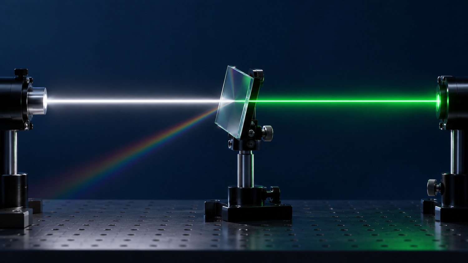
An optical filter controls the spectrum or level of light through transmission, reflection and absorption. Here the focus is wavelength selection: transmitting a useful spectral region while reducing unwanted light. A green filter does not normally turn other wavelengths into green light. It changes the balance of wavelengths already present.
Appearance is a poor specification. A visibly clear optic may reject ultraviolet or infrared radiation. Neutral density filters serve a related purpose: they aim to attenuate light relatively evenly over a stated range, rather than isolate one color.
Fig. 1 shows where incident energy can go. Rejection describes reduced transmission, not disappearing energy. Reflected light may return toward the source or reach nearby hardware; absorbed power can heat the optic.
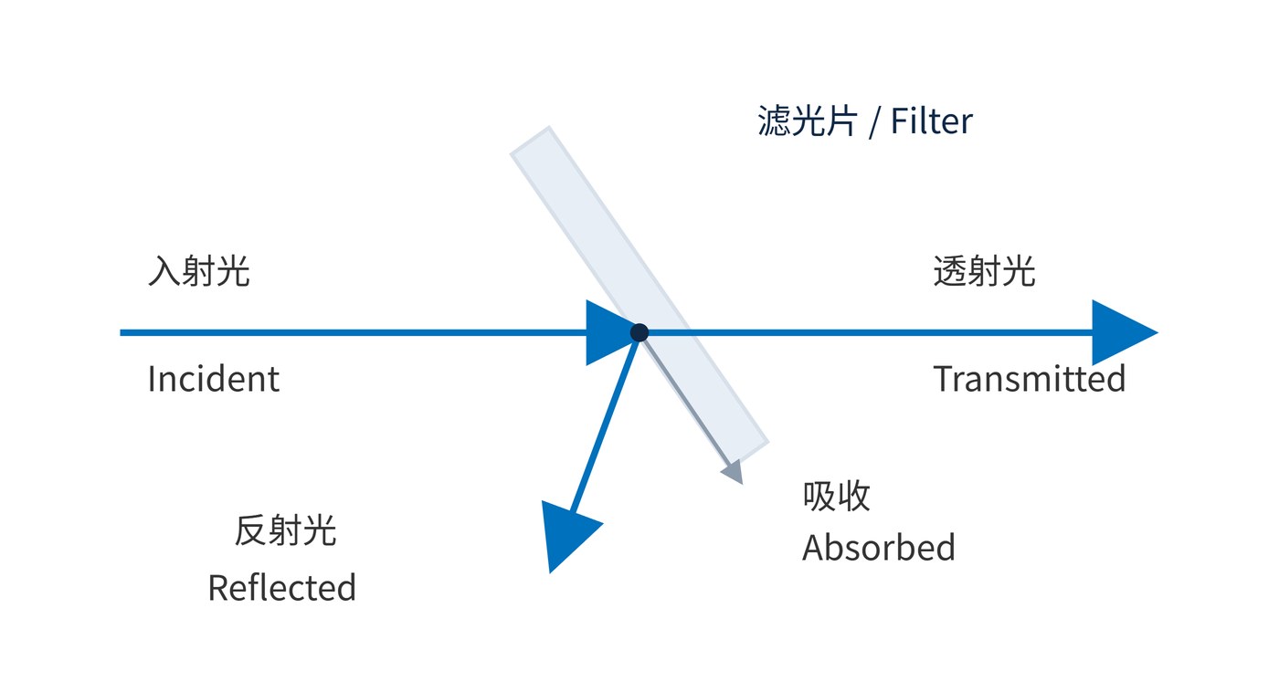
Absorptive filters exploit a material's wavelength-dependent absorption. Interference filters use the phase relationships between reflections at multiple interfaces to control transmission and reflection. A real component may combine both mechanisms. Neglecting scattering, fluorescence and other conversion processes, the energy fractions at each wavelength obey:
$$T(\lambda)+R(\lambda)+A(\lambda)=1$$
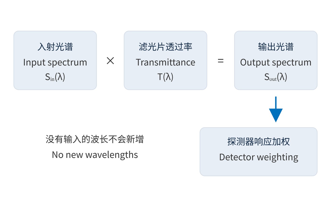
For a linear transmission path without wavelength conversion, incident spectral power density $S_{\mathrm{in}}$ is multiplied by transmittance:
$$S_{\mathrm{out}}(\lambda)=S_{\mathrm{in}}(\lambda)T(\lambda)$$
As Fig. 2 illustrates, a filter cannot transmit a wavelength that the source does not supply. Changing the source can therefore change both the output spectrum and available signal, even with the same filter.
The detector adds another weighting after transmission. Light outside its sensitive range contributes little to the measured signal, while unwanted light within that range may still matter. This is why a filter should be evaluated as part of the source–filter–detector chain, rather than as an isolated piece of glass.
Start a specification with center wavelength (CWL), full width at half maximum (FWHM) and minimum passband transmission. State angle of incidence (AOI) and polarization as well: interference filters respond to both. Optical density (OD) expresses transmission rejection, with $T$ entered as a fraction rather than a percentage:
$$\mathrm{OD}(\lambda)=-\log_{10}T(\lambda)$$
OD6 means $T=10^{-6}$, or 0.0001%, within a specified rejection range. It is not a claim about all wavelengths. Likewise, FWHM measures the separation between the half-peak crossings; it does not define the guaranteed high-transmission region.
Map the useful signal, interference and detector sensitivity before choosing a filter shape. Decide whether the task needs a transmitted band, a wavelength boundary or a rejected band. The following values illustrate a requirement, not a product specification.
| Requirement | Example | Purpose |
|---|---|---|
| Spectral position | CWL 780 nm; FWHM 20 nm | Locate the band |
| Useful transmission | Minimum ≥90% over 775–785 nm | Limit signal loss |
| Rejection | OD ≥6 over 400–750 nm and 810–1000 nm | Bound leakage in stated ranges |
| Conditions | AOI 0°; unpolarized; 23 °C; collimated beam | Make performance comparable |
The transition regions at 750–775 nm and 785–810 nm are not fully specified here. If an interference line falls there, give it an explicit transmission limit. Check clear aperture and mounting space, then account for the beam cone: a converging beam contains multiple incidence angles, so a normal-incidence curve may not describe installed performance.
Read the example as separate promises. The 20 nm FWHM locates half-peak crossings; the 775–785 nm requirement guarantees transmission only in the narrower stated interval. Neither value defines the leakage between the passband and the OD6 ranges. Keeping these requirements separate makes an acceptance discussion much less ambiguous.
Before comparing two candidate filters, put their operating conditions beside their spectral limits. Otherwise, the comparison may describe different optical setups. This check applies to both procurement documents and laboratory measurements.
Evaluate useful signal and background under comparable exposure conditions. A darker or differently colored image alone does not establish that filtering improved the measurement.
For instance, reducing ambient background helps only if enough target light remains for the measurement. In a weak-signal channel, check what reaches the detector after filtering, rather than assuming that a high peak transmission value settles the question. The useful comparison is the retained signal alongside the residual interference.
All rejected light becomes heat. Absorption creates a direct thermal load; reflected power needs a managed optical path. Narrower is always better. An overly narrow band clips useful signal and reduces tolerance to source drift and angle changes.
High OD at one wavelength eliminates background. A broadband source and detector accumulate leakage across their overlapping range. Verify the passband, full rejection range and detector response under the intended operating conditions to establish which signal actually survives.
 365nm Narrow Bandpass Filter | Ø50mm | T>90%
OT-HBP3659050
365nm Narrow Bandpass Filter; FWHM 10nm; transmission >90%; blocking OD5; size Ø50mm; AOI 0°.
 450nm Narrow Bandpass Filter | Ø50mm
OT-HBP4509050
450nm Narrow Bandpass Filter; FWHM 10nm; transmission >90%; blocking OD5; size Ø50mm; AOI 0°.
 525nm Narrow Bandpass Filter | Ø50mm
OT-HBP5259050
525nm Narrow Bandpass Filter; FWHM 10nm; transmission >90%; blocking OD5; size Ø50mm; AOI 0°.
Send us your drawing and spectral targets — an engineer replies with a feasibility check and quotation within one business day.