Original content by the OOTEE Optics editorial team, drawn from first-hand production line and inspection data. Please credit the source when republishing.
Given limits in expertise and test conditions, the theories, parameters and conclusions here carry no guarantee of absolute accuracy. For technical learning and exchange only - never the sole basis for design, acceptance or selection. Corrections welcome.
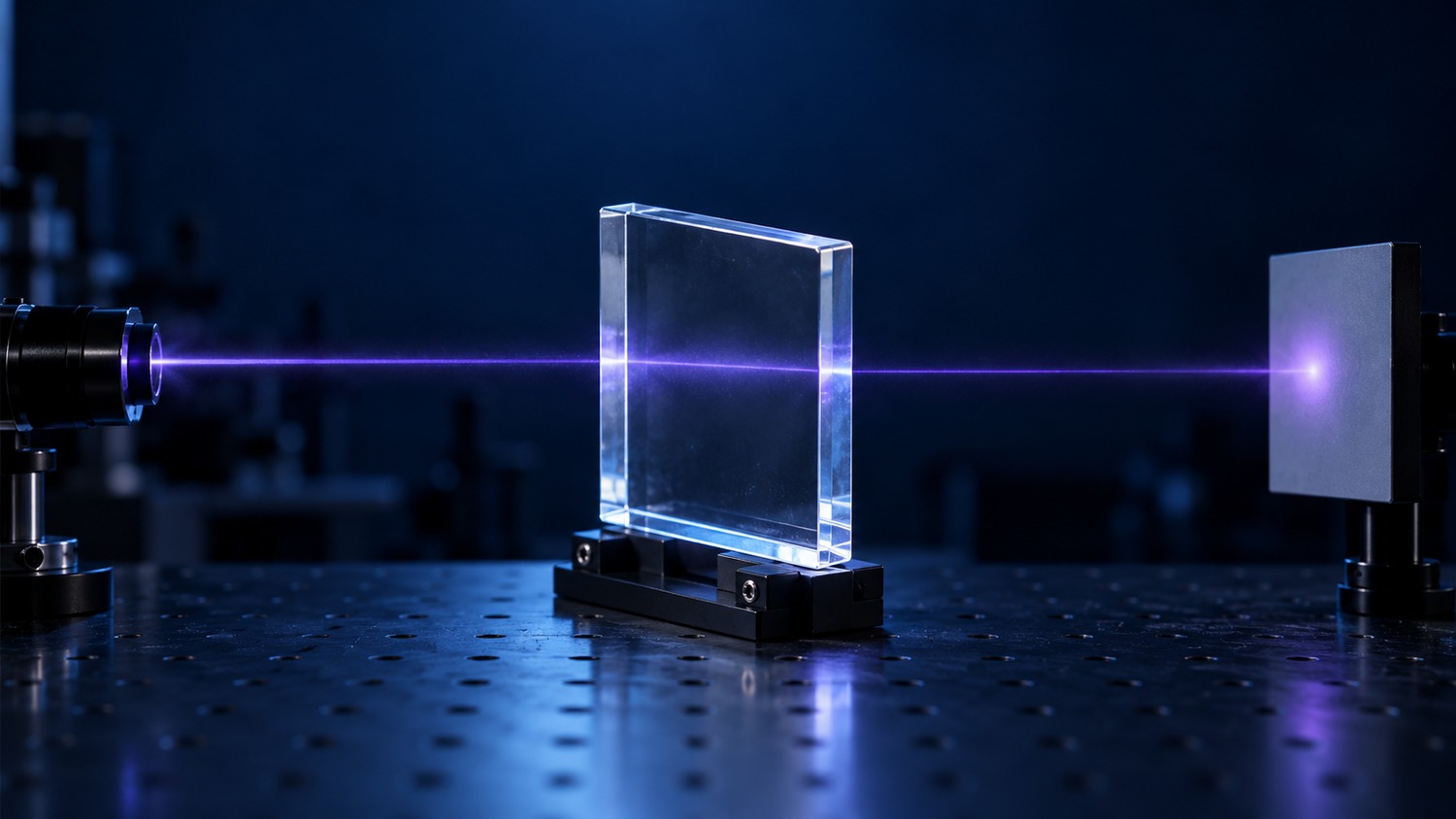
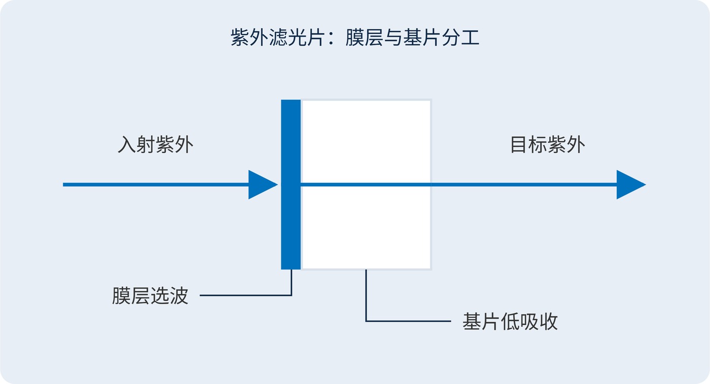
A UV filter needs two things to work together: a coating that selects wavelengths and a substrate that transmits the wanted radiation. A glass plate can look perfectly clear while absorbing strongly at 254 nm or 193 nm. No coating can recover energy lost inside that plate.
In this context, “quartz” usually means UV-grade synthetic fused silica, a high-purity, amorphous form of silicon dioxide. It should not be confused with natural crystalline quartz. Calcium fluoride (CaF₂) is a crystal. Suitable grades of both materials offer low absorption at short UV wavelengths; neither material, by itself, creates a narrow passband.
Fig. 1 separates these roles. The violet glow in the cover is a visual representation of the beam path. Shortwave UV is invisible, so its transmission cannot be judged by eye.
Shorter wavelengths carry higher photon energies and can excite electronic absorption. Metallic impurities and structural defects introduce additional absorption or fluorescence. A material’s shortwave edge is therefore not a universal on/off boundary: useful transmission depends on grade, thickness and the loss budget.
For a homogeneous substrate, internal transmission follows the Beer–Lambert approximation:
$$T_{\mathrm{int}}(\lambda,d)=\exp[-\alpha(\lambda)d]$$
Here, $\alpha$ is the absorption coefficient in $\mathrm{mm}^{-1}$ and $d$ is the optical path length in $\mathrm{mm}$. With an assumed $\alpha=0.02\,\mathrm{mm}^{-1}$, internal transmission is approximately 98.0% through 1 mm and 90.5% through 5 mm. These are illustrative values, not material specifications. Surface reflection, scatter and coating losses must be added separately.
High-purity synthetic fused silica serves 248 nm systems, with dedicated grades available for 193 nm. Appropriate calcium fluoride grades extend further into the vacuum ultraviolet. However, an infrared-grade crystal can contain impurities that make it unsuitable for UV service. A published transmission limit is not a finished-filter guarantee.
Optical density (OD) expresses attenuation at a stated wavelength:
$$\mathrm{OD}(\lambda)=-\log_{10}T(\lambda)$$
Use fractional transmission, from 0 to 1, in this equation. Substrate absorption contributes to OD but can also generate heat. High attenuation alone does not establish reflective blocking, and absorption within the passband is a direct loss.
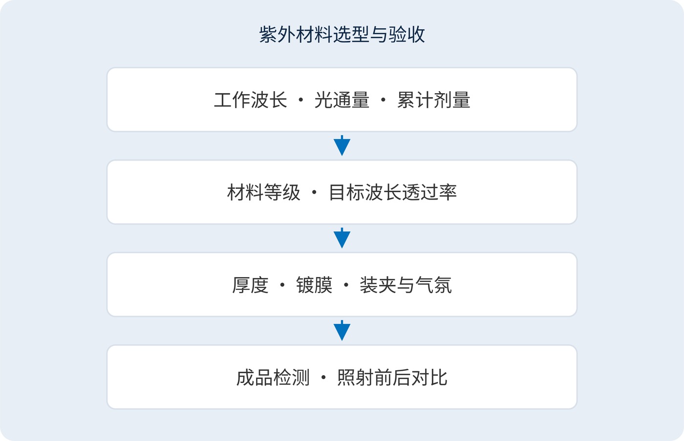
Start with wavelength, throughput and service life. Then select and verify the material grade. Fig. 2 shows why a purchase specification needs more than the word “quartz.”
| Operating case | Material assessment | Evidence needed |
|---|---|---|
| 365 nm inspection | Evaluate fused silica; some optical glasses may also qualify | Transmission at the specified thickness and fluorescence background |
| 254 nm or 248 nm | Begin with UV-grade synthetic fused silica | Absorption, coating loss and changes after exposure |
| 193 nm or shorter | Verify dedicated silica or high-purity calcium fluoride grades | Measured transmission, coating compatibility and beam-path atmosphere |
An illustrative filter requirement could state: center wavelength (CWL) 254 nm, full width at half maximum (FWHM) 10 nm, peak transmission at least 60%, blocking OD4 over 280–400 nm, and angle of incidence (AOI) 0°. These are design targets requiring feasibility checks and sample measurements. Define the beam’s angular spread as well.
Fused silica offers low thermal expansion. Calcium fluoride is softer, has cleavage planes and expands more with temperature, making edge finishing and mounting preload significant concerns. A tight rigid mount is a poor substitute for controlled clearances. High-flux specifications should also include pulse fluence, repetition rate, spot size and accumulated dose.
Ask whether a transmission report describes internal transmission or external transmission through both surfaces. Compare samples at the same thickness and wavelength. Otherwise, a difference caused by surface reflection or path length may be mistaken for a difference in material purity.
At 254 nm and 248 nm, practical checks include initial substrate loss and transmission changes during service. Weak-signal UV spectroscopy also needs a background measurement: fluorescence from the material or coating may matter even when transmission is acceptable.
At 193 nm and in the vacuum ultraviolet, surface contamination, air absorption and coating materials can limit the complete optical path. Assess nitrogen purging or vacuum operation for the actual wavelength. A transparent crystal does not establish the performance of the assembled instrument.
Grade-specific figures should come from supplier data that states wavelength and thickness.
Acceptance should describe the finished filter at its actual thickness, wavelength, beam conditions and exposure history. Visible clarity is not a UV performance measurement.
 365nm Narrow Bandpass Filter | Ø50mm | T>90%
OT-HBP3659050
365nm Narrow Bandpass Filter; FWHM 10nm; transmission >90%; blocking OD5; size Ø50mm; AOI 0°.
 450nm Narrow Bandpass Filter | Ø50mm
OT-HBP4509050
450nm Narrow Bandpass Filter; FWHM 10nm; transmission >90%; blocking OD5; size Ø50mm; AOI 0°.
 525nm Narrow Bandpass Filter | Ø50mm
OT-HBP5259050
525nm Narrow Bandpass Filter; FWHM 10nm; transmission >90%; blocking OD5; size Ø50mm; AOI 0°.
Send us your drawing and spectral targets — an engineer replies with a feasibility check and quotation within one business day.



