Original content by the OOTEE Optics editorial team, drawn from first-hand production line and inspection data. Please credit the source when republishing.
Given limits in expertise and test conditions, the theories, parameters and conclusions here carry no guarantee of absolute accuracy. For technical learning and exchange only - never the sole basis for design, acceptance or selection. Corrections welcome.

A damaged filter has a physical defect that compromises its structure or optical function. Aging is a persistent change from its original performance over time. A darker image or a different reflected color is a reason to investigate, not a diagnosis. The decision depends on the clear aperture, measured spectral performance, and the requirements of the instrument.
Start a record with the filter identifier, orientation, operating hours, date of the symptom, and illuminated area. Keep photographs under repeatable lighting. An acceptance scan or commissioning measurement is the best baseline. A qualified spare of the same specification is useful when no baseline exists, but unit-to-unit variation prevents that comparison alone from proving aging.
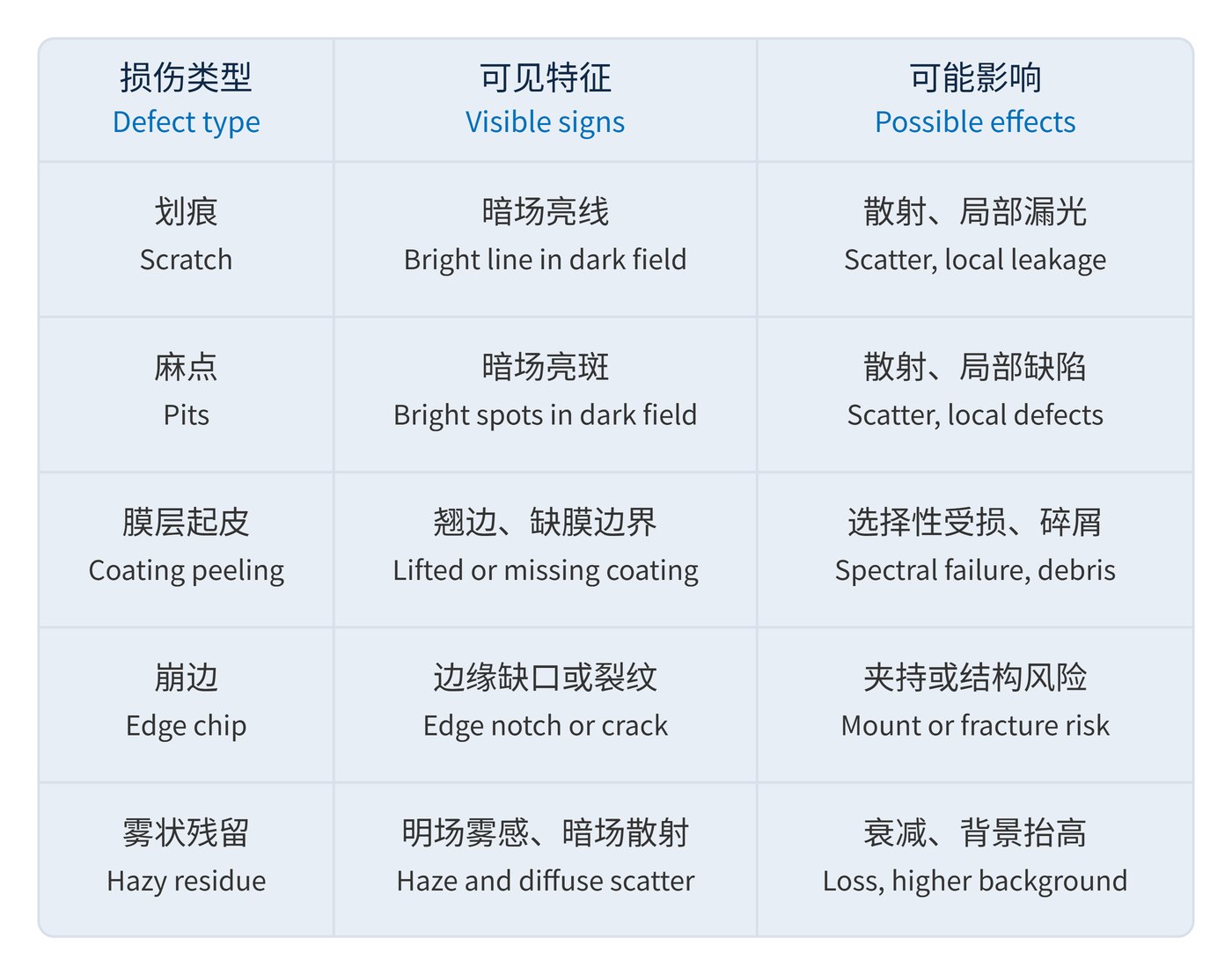
Fig. 1 connects visible symptoms to possible consequences. Appearance cannot quantify blocking performance. Hazy residue is not proof of permanent coating damage: isolate the suspect part and obtain comparable measurements before assigning that diagnosis.
Record center wavelength (CWL), full width at half maximum (FWHM), peak transmittance, and blocking optical density (OD). Match angle of incidence (AOI), polarization, temperature, beam diameter, and measurement position. Check the effect of incidence angle before interpreting a shift. Measure a reference first to check the instrument, then remount and measure the suspect filter 3 times. Include the center and the peripheral positions actually used.
Express peak loss relative to the baseline rather than confusing it with percentage points:
$$L_T=\frac{T_{\mathrm{peak},0}-T_{\mathrm{peak},t}}{T_{\mathrm{peak},0}}\times100\%$$
A change from 90% to 85.5% is a loss of 4.5 percentage points, or 5% relative. Subscripts 0 and t denote the baseline and current measurement. For blocking, compare the specified wavelengths and use fractional transmittance in the equation:
$$\mathrm{OD}(\lambda)=-\log_{10}T(\lambda)$$
OD6 means 0.0001% transmittance; OD5 means 0.001%, a tenfold increase in leakage. A measurement cannot verify OD6 unless its stray-light performance and dynamic range support that claim. The measurement limitations are discussed in NIST guidance on spectral transmittance.
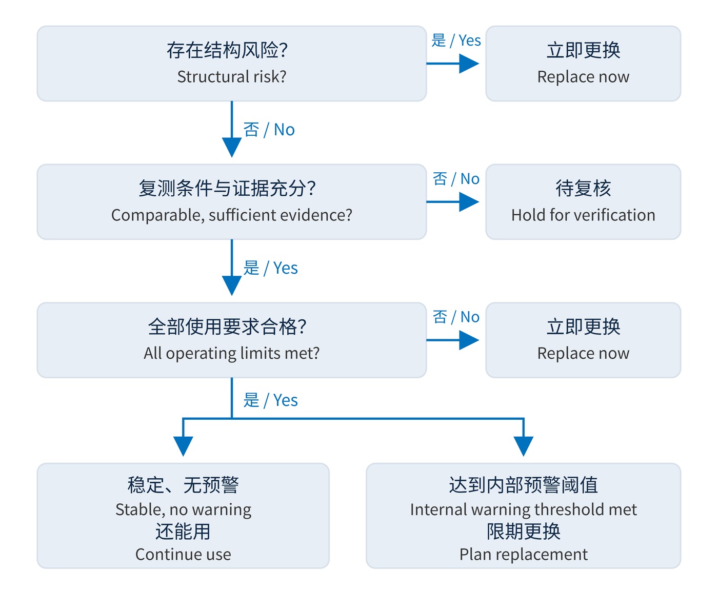
The thresholds below are an example of internal screening for ordinary, non-safety applications, not an industry rejection standard. Drawing limits and system tolerances take priority. Treat a change as credible only when it exceeds measurement uncertainty and repeats. Fig. 2 includes a hold for inconclusive evidence: missing evidence is not a pass.
| Finding | Disposition |
|---|---|
| No structural risk; all requirements met; relative peak loss below 5%, with no worsening trend | Continue use and retain the baseline for scheduled checks |
| Relative peak loss at least 5% but below 10%, or relative FWHM growth at least 10%; all operating requirements still met | Plan replacement, shorten the inspection interval, and have a spare ready before the next service |
| Any critical requirement failed, or cracks, loose fragments, progressing peeling, or unstable mounting present | Replace immediately and remove the filter from its original duty |
A relative peak loss of 10% or more should suspend release pending verification; replace the part if it exceeds the predetermined operating limit. Consider a filter with CWL 780 nm, FWHM 20 nm, and specified OD6 blocking. A measured width of 22 nm warrants investigation. Calculate each width at half of that scan's own peak, and rule out instrument bandwidth and AOI differences. Broadening can admit more background, but measurement changes can also produce it; broadening alone does not prove coating aging.
In fluorescence instruments, a narrow bandpass filter can retain its peak transmission while leaking more excitation light. Check blocking and a blank sample as well as the passband. For machine vision, verify contrast, exposure, and field uniformity. A large measurement beam can average away a defect that affects a small working region.
Laser protection and other safety duties require a different disposition: remove a suspect part from protective service immediately and follow the applicable requirements and qualified testing. The screening thresholds above are unsuitable for that decision. Never test protective effectiveness by eye.
An intact appearance does not establish adequate blocking, and a scratch does not automatically condemn the whole filter. Calendar age cannot replace a performance trend. A reading at 780 nm cannot replace scans of the complete passband and specified blocking range. If the reference also becomes darker, investigate the source, detector, and measurement chain first. A useful inspection record includes defect locations, comparable spectra, uncertainty, and the reason for the disposition so the next check can reproduce the decision.
 365nm Narrow Bandpass Filter | Ø50mm | T>90%
OT-HBP3659050
365nm Narrow Bandpass Filter; FWHM 10nm; transmission >90%; blocking OD5; size Ø50mm; AOI 0°.
 450nm Narrow Bandpass Filter | Ø50mm
OT-HBP4509050
450nm Narrow Bandpass Filter; FWHM 10nm; transmission >90%; blocking OD5; size Ø50mm; AOI 0°.
 525nm Narrow Bandpass Filter | Ø50mm
OT-HBP5259050
525nm Narrow Bandpass Filter; FWHM 10nm; transmission >90%; blocking OD5; size Ø50mm; AOI 0°.
Send us your drawing and spectral targets — an engineer replies with a feasibility check and quotation within one business day.



